TP-6519 8/1732 Section 3 Troubleshooting
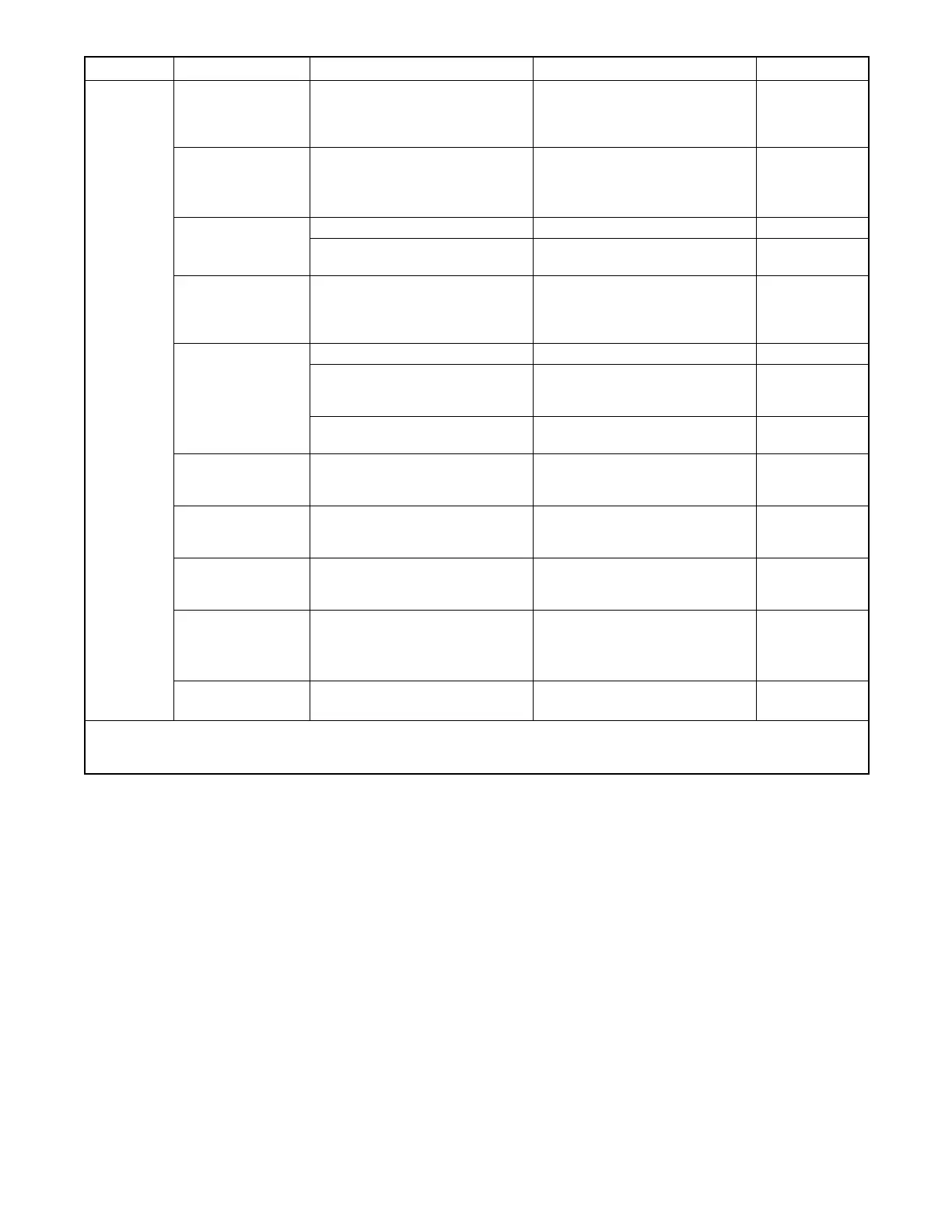
Problem ReferenceCorrective ActionTestPossible Cause
No output
voltage,
continued
Alternator or control
system
Perform separate excitation
procedure to isolate the problem
to the alternator or the control
system.
Troubleshoot the alternator or
control system components as
described below and elsewhere in
this table.
Section 5.2
SCR module Check auxiliary winding fuse F1
(lead 55).
Replace SCR module and test
voltage.
Check auxiliary winding fuse F1
(lead 55).
Replace SCR module and test
voltage.
Section 5.13.2
Section 4.8
Controller
Check the controller settings. Adjust controller settings. Section 4.5
Test the controller as described in
Section 3.4.
See Section 3.4. Section 3.4
Open wiring,
terminal, or pin in
buildup circuit or
SCR module circuit
Check fuses and wiring. Replace fuses or wiring as
necessary.
Section 5.13.2
Section7W/D
Brushes
Inspect brushes. Replace brushes if worn. Section 5.6
Check for brushes sticking in
brush holder or broken brush
spring.
Replace brush spring or brush
assembly.
Section 5.6
Check that brush holder is
securely mounted.
Tighten brush holder screws. Section 5.6
Rotor slip rings dirty
or corroded
Check slip ring condition. Clean slip rings as described in
Section 5.5. Machine slip rings if
necessary.
Section 5.5
Rotor (open,
grounded, or
shorted windings)
Check voltage and continuity as
described in Section 5.4.
Repair or replace rotor if indicated
by the tests.
Section 5.4
Stator (open,
grounded, or
shorted windings)
Check voltage and continuity as
described in Section 5.3.
Repair or replace the stator if
indicated by the test results.
Section 5.3
Flash relay (K3) on
controller
Check fuse F2.
Check flash LED 1 on controller.
Replace fuse F2.
If LED1 indicates power to the
relay but the relay does not
operate, replace controller board.
Section 5.13.2
Section 4.6
Aux. winding fuse
blown (lead 55)
Check fuse.
If fuse blows again, check stator.
Replace blown fuse.
If fuse blows again, check stator.
Section 5.13.2
Section 5.3
* ADC-RES controller only. The DC-RET controller settings cannot be adjusted in the field.
W/D = Wiring Diagram(s) (Section 7) S/S = Generator Set Specification Sheet O/M = Generator Set Operation Manual
I/M = Generator Set Installation Manual Engine S/M = Engine Service Manual
 Loading...


