TP-6953 7/19 107Section 6 Cooling System
Figure 6 -10 Reinstall Heat Exchanger
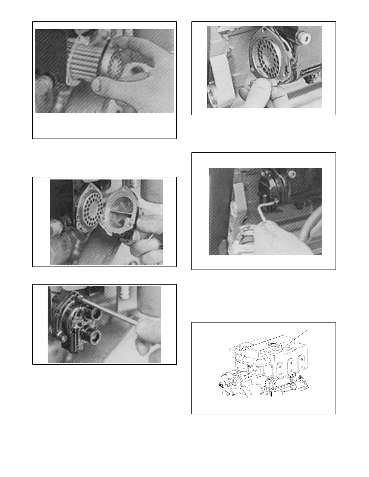
14. Reassemble the O-ring and front cover and tighten
the screws. See Figure 6-11 and Figure 6 -12.
Figure 6 -11 Reinstall the O-ring and Front Cover
Figure 6 -12 Tigh ten the Front Cover Screws
15. Fit the circlip and flange back into position. See
Figure 6-13.
Figure 6-13 Heat Exchanger’s Circlip
16. Reassemble the O-ring and rear cover and tighten
the screws. See Figure 6-14.
Figure 6-14 Rear Cover of Heat Exchanger
17. Remove the pressure cap and refill the coolant.
See Section 6.4 for details on coolant check and fill
instructions. The level should be approx. 2 cm
(0.75in.)belowthefillinghole.
1
1. Pressure cap
Figure 6-15 Pressure Cap Location
18. Replace the pressure cap.
 Loading...


