TP-6953 7/19174 Section 10 Alternator Component Testing and Adjustment
10.2 Separate Excitation
To determine the cause of no- or low-AC output, refer to
the troubleshooting flowchart in Figure 10-1. Before
beginning the test procedures, read all of the safety
precautions at the beginning of this manual. Many of the
test procedures include additional safety precautions.
No Generator Output
Separate Excitation
Output within
Specifications
Check Rotor
Check Wiring
and V oltage Regulator
(integrated in Controller)
Check Stator
TP-6878-3
Erratic or No Output
Figure 10 -1 General Troubleshooting
Use the following procedure to separately excite the
generator using an external voltage source (a 12-volt
battery).
Hot engine and exhaust system.
Can cause severe injury or death.
Do not work on the generator set until
it cools.
WARNING
Servicing the alternator. Hot parts can cause severe
injury or death. Avoid touching the alternator field or exciter
armature. When shorted, the alternator field and exciter
armature become hot enough to cause severe burns.
Separately exciting the alternator can determine the
presence of a faulty voltage regulator or determine if a
running fault exists in the rotor and/or stator. An
alternator component that appears good while static
(stationary) may exhibit a running open or short circuit
while dynamic ( moving). Short circuits can be caused
by centrifugal forces acting on the windings during
rotation or insulation breakdown as temperatures
increase.
1. Stop the generator set. Refer to the operation
manual as needed.
2. Disconnect the FP/FN connector.
3. Connect an ohmmeter to the exciter field winding
and measure the resistance. Note and record the
ohmmeter reading.
4. Disconnect the ohmmeter after measuring the
resistance.
5. Connect a DC ammeter, 10-amp fuse, and a
12-volt battery to the positive (FP) and negative
(FN) exciter leads as shown in Figure 10-2. Note
and record the ammeter reading.
The approximate ammeter reading should be
battery voltage divided by the specified exciter field
winding resistances (cold). See Section 1,
Specifications, for the values.
Example:
12 V olts (Battery Voltage)
2.1 amps
Exciter Field
Winding Current
=
5.8 Ohms
Exciter Field Winding
Resistance
-+
AC
F+
F-
AC
AC
+
TP-6878-3
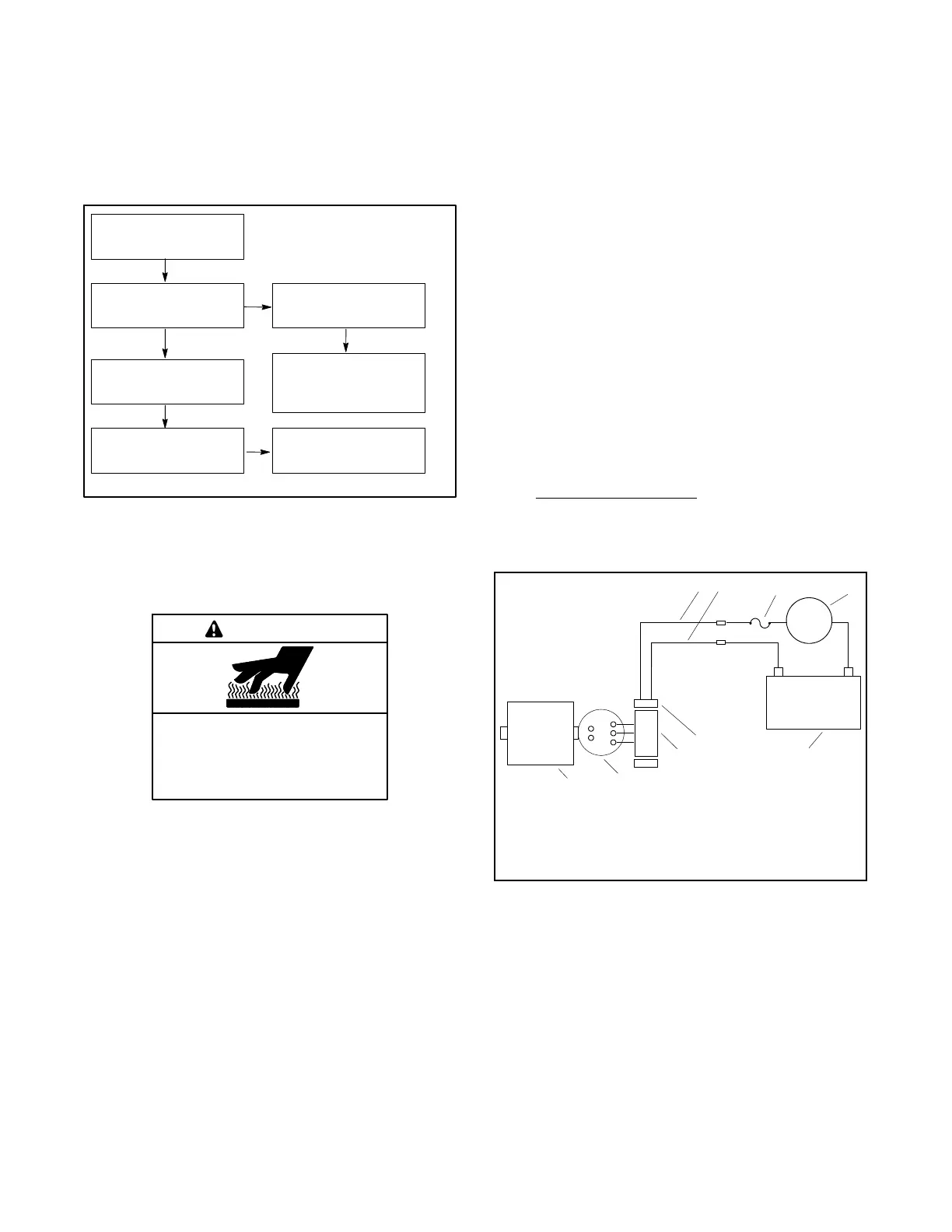
1. FN lead (disconnected in step 2
2. FP lead (disconnected in step 2
3. 10-amp fuse
4. DC ammeter
5. 12-volt battery
FPFN
6. Exciter field winding
7. Exciter armature
8. Rectifier module
9. Main field (rotor)
A
-
9
12
3
4
5
6
7
8
Figure 10-2 Separate Excitation Connections
6. Start the generator set. Refer to the operation
manual as needed.
7. Check the ammeter values.
Unstable ammeter reading. An increasing meter
reading indicates a shorted exciter field. A
decreasing meter reading to zero, or unstable
reading, suggests a running open in the exciter.
Stable ammeter reading. If the ammeter is
stable, continue with the next step.
 Loading...


