TP-6953 7/19184 Section 10 Alternator Component Testing and Adjustment
No
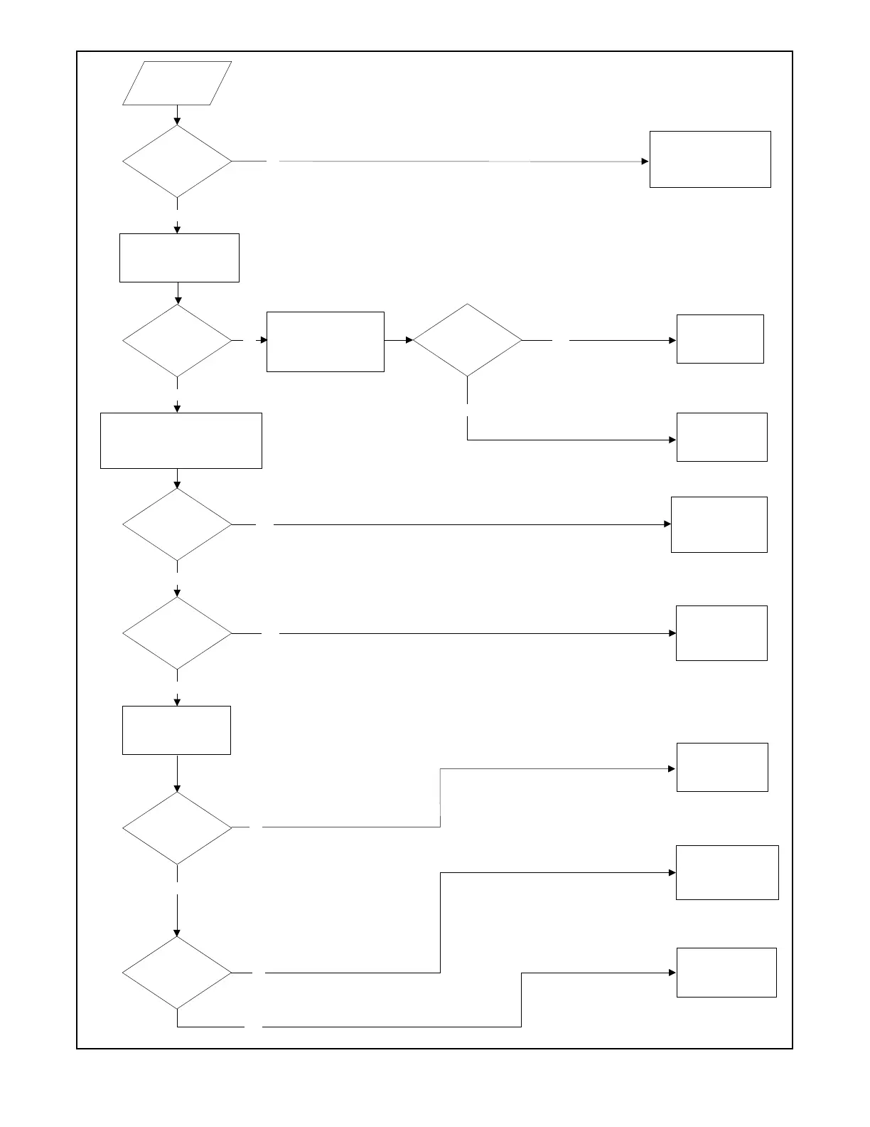
Generator does
not make
voltage
ArebothLEDson
activator board
illuminated?
No
Yes
Remove 14-pin connector
from activator board and
connect multimeter measuring
mADC between pins 1(-) and
6(+), measuring LED current.
Note: Some multimeters have a single
position on the selection dial for
measuring mA (both for AC and DC).
These meters require selection of DC by
pressing an additional button or switching
a selection switch. Make sure that the
multimeter is set to read DC current.
Is LED current
>50 mA when
generator set is
running?
Check wiring to
controller. Verify that
the controller mode
expects output
voltage.
Yes
With generator set off, reconnect 14-pin
connector. Disconnect FP and FN at the
fast-on terminals between the activator
board and the exciter field. Connect a
multimeter measuring resistance
between FP and FN of the exciter field.
Yes
Is field resistance
<10Ω?
Verify that exciter field
is connected (check
wiring for broken or
disconnected wires and
check field windings for
dark coloring).
Yes
Is field resistance
>4 Ω?
Verify that exciter field
is not short circuited
(check wiring for
rubbing and field
windings for dark
coloring).
Yes
Remove FP and FN and
connect leads to a
12-volt battery (polarity is
not important). Start
generator set.
No
Check rotor field
resistance, exciter
armature resistance,
and rotating rectifier
module.
Is generator
output voltage
greater than rated
voltage when
running?
Connect a second multimeter
measuring DC voltage in
parallel with the multimeter
measuring LED current. This
meter is measuring LED
voltage.
Is LED voltage
>2.0 VDC ?
Fuse in LED current
multimeter is blown.
Replace or use a
different meter for
troubleshooting.
Remove 14-pin connector
from activator and check for
batteryvoltageonpins7and
8 when the generator set is
running. If voltage is present,
activator board may be faulty.
Check auxiliary winding
resistance. Check
voltage between 60, 61,
and 62. Voltage between
at least two of the wires
should be >25 VAC.
Is voltage between
aux. windings 60
and62>25V?
Yes
Check connections to
activator board and
exciter field for burned
sections (intermittent
connections)
No
No
No
Yes
No
 Loading...


