TP-6953 7/19192 Section 11 Alternator Component Testing and Adjustment
11.3 LED Optic Board Test
The following procedure provides information on testing
the LED optic board. Certain steps require that the
generator set be running. When the generator set is not
running, disable the generator set. See the safety
precautions listed below. Disconnect all load from the
generator set during this test.
To test the LED optic board, the following item is needed:
D Flashlight
Accidental starting.
Can cause severe injury or death.
Disconnect the battery cables before
working on the generator set.
Remove the negative (- ) lead first
when disconnecting the battery.
Reconnect the negative (- ) lead last
when reconnecting the battery.
WARNING
Disabling the generator set. Accidental starting can
cause severe injury or death. Before working on the
generator set or equipment connected to the set, disable the
generator set as follows: (1) Press the generator set off/reset
button to shut down the generator set. (2) Disconnect the
power to the battery charger, if equipped. (3) Remove the
battery cables, negative (- ) lead first. Reconnect the negative
(- ) lead last when reconnecting the battery. Follow these
precautions to prevent the starting of the generator set by the
remote start/stop switch.
Hazardous voltage.
Can cause severe injury or death.
Operate the generator set only when
all guards and electrical enclosures
areinplace.
Moving parts.
WARNING
Disconnecting the electrical load. Hazardous voltage can
cause severe injury or death. Disconnect the generator set
from the load by turning off the line circuit breaker or by
disconnecting the generator set output leads from the transfer
switch and heavily taping the ends of the leads. High voltage
transferred to the load during testing may cause personal
injury and equipment damage.
Testing the photo transistor circuit board. Hazardous
voltage can cause severe injury or death. When the end
cover is removed, do not expose the photo transistor circuit
board mounted on the generator set end bracket to any
external light source, as exposure to light causes high voltage.
Keep foreign sources of light away from the photo transistor
circuit board during testing. Place black electrical tape over
the LED on the circuit board before starting the generator set.
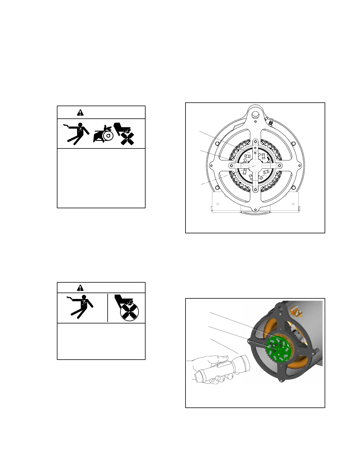
1. Remove the junction box panels from the
generator end of unit and remove the LED o ptic
board holder/LED optic board. See Figure 11 -3.
TP-6783-3
1. FRX activator board
2. LED optic board holder
3. LED optic board
1
2
3
Figure 11 -3 FRX Activator Board with LED Optic
Board Installed.
2. Refer to the generator set operation manual for
starting/stopping procedures. With the generator
set running at no load, shine a flashlight at the
exposed photo transistor on the FRX activator
board. See Figure 11-4.
1
2
3
1. FRX activator board
2. Photo transistor
3. Flashlight
TP-6783-3
Figure 11 -4 Flashlight Test on FRX Activator Board
 Loading...


