234 Section 12 Paralleling System Information TP-6953 7/19
Fail to Close Delay
The Fail to Close Delay determines the time that the
controller will hold the close signal on during a close
attempt. If the breaker status does not indicate that it is
closed within the time allocated by the F ail to Close
Delay, the controller will remove the close signal and
issue a Breaker Close Attempt Fault. After the controller
has seen a number of close attempt faults equal t o the
breaker close attempts, the controller will issue a Failure
to Close. Failures to Close may be caused because the
breaker requires an abnormally long time to close, but
they are typically caused by wiring errors, external
protective relay settings, or incorrect motor operator
specifications/operating voltage.
Range: 0.1 sec - 30.0 sec
Default: 0.3 sec
Breaker Reclose Time
The Breaker Reclose Time controls the time delay
between close attempts on the breaker. This is intended
to allow the breaker to reset to a normal state and to
operate properly on the subsequent reclose attempt.
Range: 0.5 sec - 30.0 sec
Default: 2.0 sec
Breaker Close Attempts
The Breaker Close Attempts indicates how many failed
attempts to close the breaker the controller will accept
before issuing a Fail to Close fault and requiring a fault
reset to re-attempt breaker closure.
Range: 1 - 100
Default: 3.0 sec
Generator Paralleling Breaker
The Generator Paralleling Breaker is a Status
parameter that indicates the internal measured position
of the paralleling breaker. The parameter is displayed
under Metering -> Paralleling Metering and under
Generator Info -> Parallel Operation -> Synchronization
Setup as Connected to Bus.
Range: False - True
Default: **STATUS**
Speed Bias
The amount that the controller is attempting to adjust the
output frequency of the generator (100% bias = +5% on
the engine speed, -100% = -5% on the engine speed).
The controller adjusts the Speed bias to match
frequency and phase with the paralleling bus.
Note: The Speed Bias can also be controlled by an
external device if the External Bias Inputs
Enabled parameter is true, the Stand Alone
Operation parameter is false, no other
generators are visible on the PGEN
communications channel, and the voltage
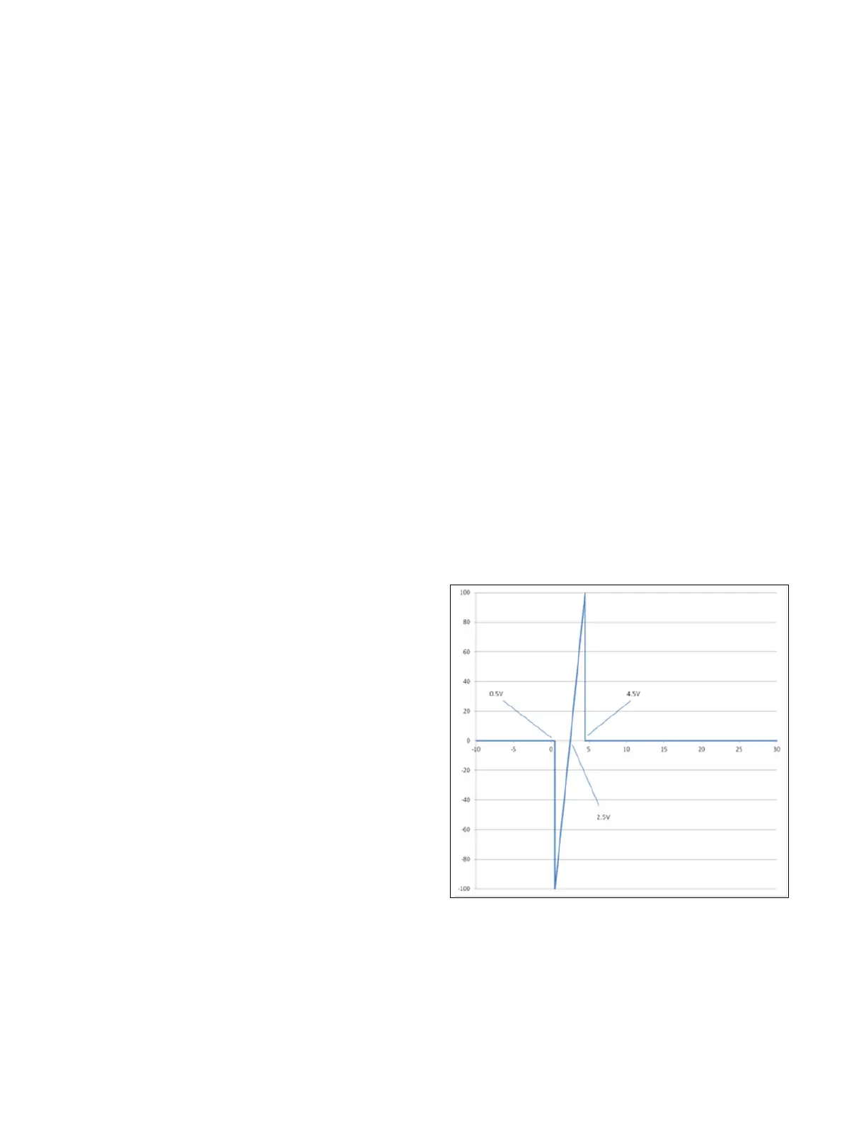
applied to the speed bias input is between 0.5V
and 4.5V.
The External Speed Bias Input (SBP and SBN) is a
voltage measuring channel capable of reading from
-10V to 30V DC. The input is normally pulled down to
-3.3V, but can be overridden by applying a voltage to the
input.
The voltage that the controller sees on the voltage
measuring channels is visible in the Analog Voltage
Input Metered Relative Value under the Programmable
Analog Voltage Input I08 heading. The input is polarity
sensitive.
The Speed Bias is interpreted by the controller as
illustrated in Figure 12-8.
Range: -100.00% – 100.00%
Default: 0.00% **Not Writable**
Figure 12-8 Speed Bias
 Loading...

