TP-6953 7/19 271Section 15 Alternator Disassembly/Reassembly
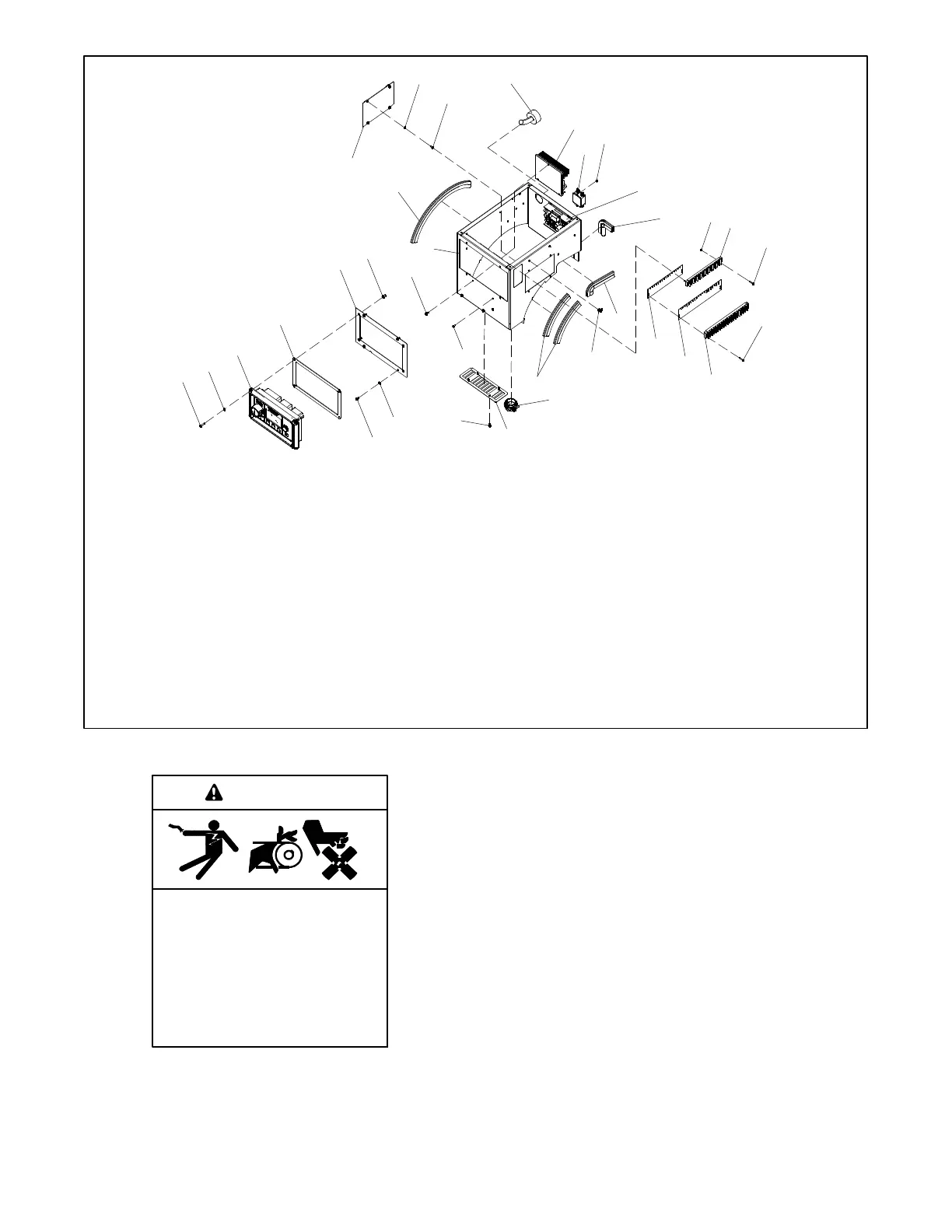
1. Plain washers
2. Pan head screws
3. Junction box harness
4. Battery charger assembly
5. RFI power line filter
6. Hex nuts
7. Activator board assembly
8. Pan head screws
9. Hex nuts
10. Push-on trim seal
11. Terminal strip
12. Pan head screws
13. Terminal block
14. Strip marker
15. Strip marker
16. Push-on trim seal
17. Tie wrap snap-in base
18. Push-on trim seal
19. Cable connector
20. Air inlet guard
21. Crimptite screws
22. Pan head screws
23. Pan head screws
24. Controller assembly
25. Controller cover gasket
26. Controller panel
27. Threaded inserts
28. Thread forming screws
29. Junction box
30. Push-on trim seal
31. Circuit breaker cover
1
2
3
4
5
6
7
8
9
10
6
11
12
12
13
14
15
16
17
18
19
20
21
22
1
2
23
24
1
25
26
27
28
29
30
31
TP6954
Figure 15 -2 Junction Box and Controller Components, Typical (Parts Shown May Vary Slightly Between Models)
Accidental starting.
Can cause severe injury or death.
Disconnect the battery cables before
working on the generator set.
Remove the negative (- ) lead first
when disconnecting the battery.
Reconnect the negative (- ) lead last
when reconnecting the battery.
WARNING
Disabling the generator set. Accidental starting can
cause severe injury or death. Before working on the
generator set or equipment connected to the set, disable the
generator set as follows: (1) Press the generator set off/reset
button to shut down the generator set. (2) Disconnect the
power to the battery charger, if equipped. (3) Remove the
battery cables, negative (- ) lead first. Reconnect the negative
(- ) lead last when reconnecting the battery. Follow these
precautions to prevent the starting of the generator set by the
remote start/stop switch.
 Loading...

