TP-6953 7/19274 Section 15 Alternator Disassembly/Reassembly
558866
1
3
24
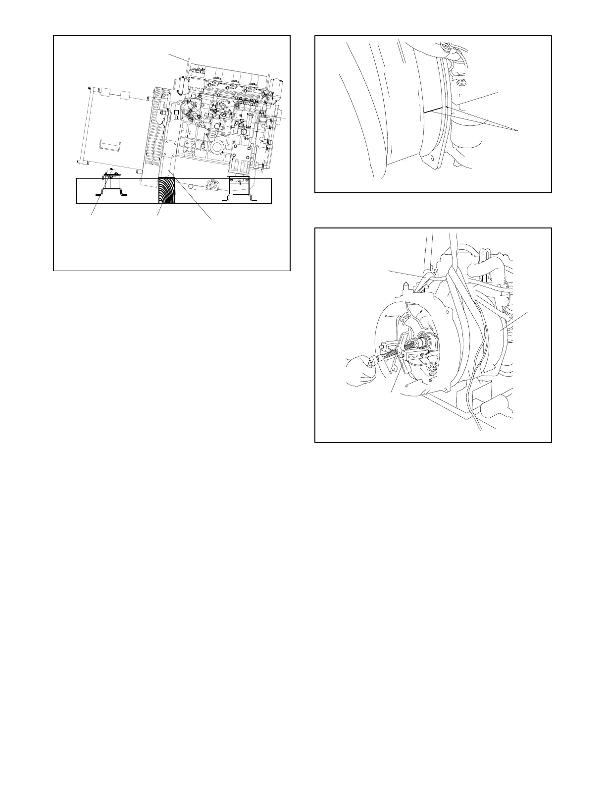
1. Lifting eye
2. Backplate
3. Wood block
4. Vibromounts
Figure 15 -5 Supporting the Generator, Typical
10. Use a permanent marker (or scribe) and make an
alignment mark on the stator and engine adapter
for r eference during reassembly. See Figure 15-6.
11. Install a sling capable of handling the weight of the
stator housing on the stator housing. See
Figure 15-7.
12. Use a two-jaw puller to pull the end bracket/stator
assembly from the bearing on the rotor shaft. See
Figure 15-7.
13. Remove the stator assembly from the rotor.
Remove or rotate the fan guard, if necessary, to
clear the vibromounts.
14. Use a permanent marker (or scribe) and make an
alignment mark to show the fan’s position on the
rotor/drive disc assembly for reference during
reassembly.
15. Remove the eight screws and washer attaching the
alternatorfantotherotor. SeeFigure15-8.
5588613
1
1. Alignment marks
Figure 15-6 Alignment Marks on Stator and Engine
Adapter
558867
1. Sling
2. Fan guard
3. Two-jaw puller
1
2
3
Figure 15-7 Stator Assembly Removal
 Loading...

