TP-6953 7/19276 Section 15 Alternator Disassembly/Reassembly
15.3 Reassembly
Refer to Section 1, Specifications for Torque Values and
Assembly Specifications and Appendix C, General
Torque Specifications during reassembly.
Note: For 35- 40 kW generator sets equipped with
4PX/4QX alternators, refer to Section 16 for
procedure to reassemble exciter, activator board,
and LED optic board.
Note: Some hardware assembly requires the use of
Loctiter 242 Blue or equivalent to the bolt
threads.
1. Use solvent to clean any threaded component
holes and hardware that contain used thread
sealant if they will be reused. Allow the
components and hardware to dry.
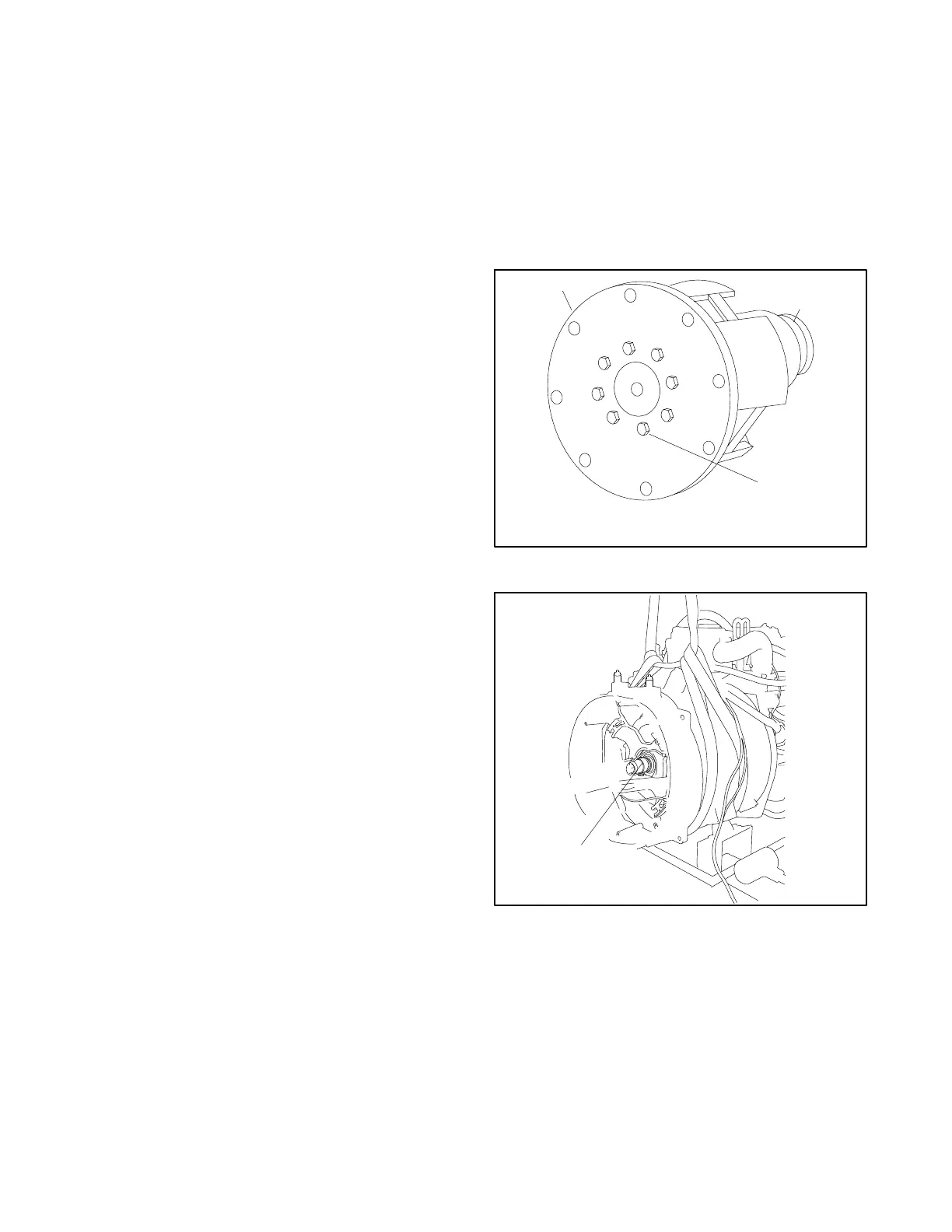
2. Clamp the rotor in a soft-jaw vise. Apply thread
sealant to the bolt threads. Install the drive disc(s)
on the rotor and torque the eight bolts to
specifications. See Figure 15-11.
3. Apply thread sealant to the bolt threads. Place the
rotor/drive disc assembly on the engine flywheel
and torque the eight washers and bolts to
specifications.
4. Apply thread sealant to the bolt threads. Align the
fan to the rotor/drive disc assembly using the
marks created in the disassembly procedure.
Install the fan to the drive disc using eight screws
and washers and torque to specifications.
Note: Install the fan with the flange side facing
away from the flywheel.
5. Apply multi- purpose grease to the O-ring and
install in the end bracket bearing bore. See
Figure 15-12. Use a sling to support the stator
assembly while installing the stator over the rotor.
Be careful not to damage the rotor.
6. Check that the alignment marks on t he stator
housing and engine adapter match. See
Figure 15-13.
7. Install the four long studs thru the stator assembly
holes and thread into the engine adapter.
8. Align the end bracket holes over the studs and
position the end bracket over the rotor bearing
9. Install the nuts on the studs and torque the
studs/nuts to specifications.
10. Use the hoist to raise the alternator end. Remove
the wood block from under the backplate. Lower
the generator set and install a bolt, a large washer,
a small washer, and a locknut on each vibromount.
Remove the hoist/sling equipment.
5588610
1
2
3
1. Drive disc(s) 2. Rotor 3. Bolt
Figure 15-11 Drive Disc(s) Installation
55886121. O-ring
1
Figure 15 -12 Stator Installation
Loctiter is a registered trademark of the Henkel Corporation.
 Loading...

