2 TT-1596 8/22
Circuit Breaker Kits
If the APM is not installed within sight of the generator
sets, local codes may require the installation of circuit
breakers near the APM. Circuit br eaker kits are
available for installation inside the APM enclosure.
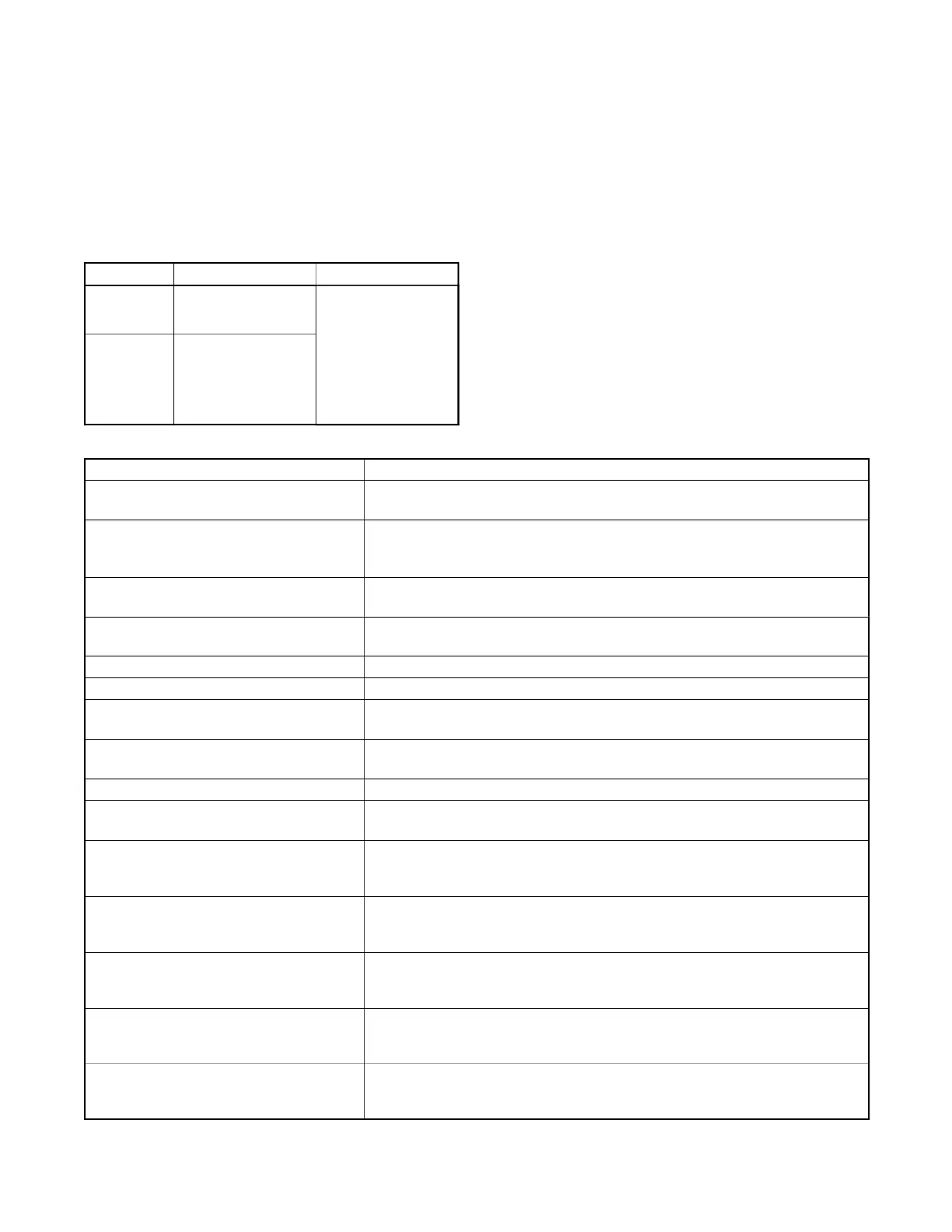
Figure 2 shows the circuit breaker kit numbers for the
14RESA, 14RCA, 20RESA/B/C/D and 20RCA
generator sets. Verify that you have the correct kit for
your generator set model.
Model Circuit Breaker Kit APM Kit
14RESA
14RCA
14RCAL
GM86368-KP1-QS
GM85144-KP1-QS
20RESA
20RESB
20RESC
20RESD
20RCA
20RCAL
GM86369-KP1-QS
Figure 2 Kit Numbers
Other Accessories
Other compatible accessor ies include:
D Programmable Interface Module (PIM)
D OnCuer Plus Generator Management System
If OnCue Plus will be used, a unique OnCue activation
code is required for each generator set. Two activation
codes are provided with the APM kit.
Definitions
Some terms used in these instruction s are defined in
Figure 3.
Term
Definition
Automatic paralleling module (APM) The box that contains the contactors and optional circuit breakers.
See Figure 1.
Single-phase paralleling system System that includes the APM, two generator sets, current transformers
(CTs), transfer switch, load management device, optional PIM, and
optional OnCuer Plus. See Figure 7.
Generator management Determination of the number of generator sets needed to supply the
load and logic for stopping one of the generator sets.
Load management Shedding and adding loads using the load control module (LCM), load
shed kit, or RXT ATS with combined interface/load management board.
Generator 1 The generator set connected to the left-side contactor in the APM.
Generator 2 The generator set connected to the right-side contactor in the APM.
Primary generator The generator set whose RDC2 controller is controlling the RBUS
network.
Secondary generator The generator set whose RDC2 controller is monitoring but not
controlling the RBUS network.
First-order generator The generator set that is not stopped by generator management.
Second-order generator The generator set that is turned off by generator management when it
is not needed.
Runtime order selection The generator with the fewest number of hours of operation is selected
as the first order generator set. Runtime order selection may cause
generators 1 and 2 to alternate order. See Section 5.3.2.
Manual order selection The generator set that has last been taken off-line (see Auto-Off) is
always the second order generator set. Runtime hours are ignored.
See Section 5.3.2.
Auto-Off Pressing the AUTO and OFF buttons simultaneously on one generator
set’s RDC2 controller removes that generator set from the bus. The
other generator set will start if it is offline. See Section 5.3.2.
Auto-Run Pressing the AUTO and RUN buttons simultaneously on either
generator set places generator management in runtime hour selection
mode. See Section 5.3.2.
Auto-Discovery A required procedure after paralleling system installation,
auto-discovery confirms that the system components are connected
correctly and communicating as required. See Section 4.4.
Figure 3 Definitions
 Loading...