TP--6805 8/15 165Appendix
Appendix B Common Hardware Application Guidelines
Use the information below and on the following pages to
identify proper fastening techniques when no specific
reference for reassembly is made.
Bolt/Screw Length: When bolt/screw length is not given,
use Figure 1 as a guide. As a general rule, a minimum
length of one thread beyond the nut and a maximum
length of 1/2 the bolt/screw diameter beyond the nut is
the preferred method.
Washers and Nuts: Use split lock washers as a bolt
locking device where specified. Use SAE flat washers
with whiz nuts, spiralock nuts, or standard nuts and
preloading (torque) of the bolt in a ll other applications.
See Appendix C, General Torque Specifications, and
other torque specifications in the service literature.
G--585
Preferred Nut/Bolt Clearance
Unacceptable Nut/Bolt Clearance
1
2
3
1. 1/2 of bolt diameter
2. Min. 1 full thread beyond top of nut
3. Below top of nut
Figure 1 Acceptable Bolt Lengths
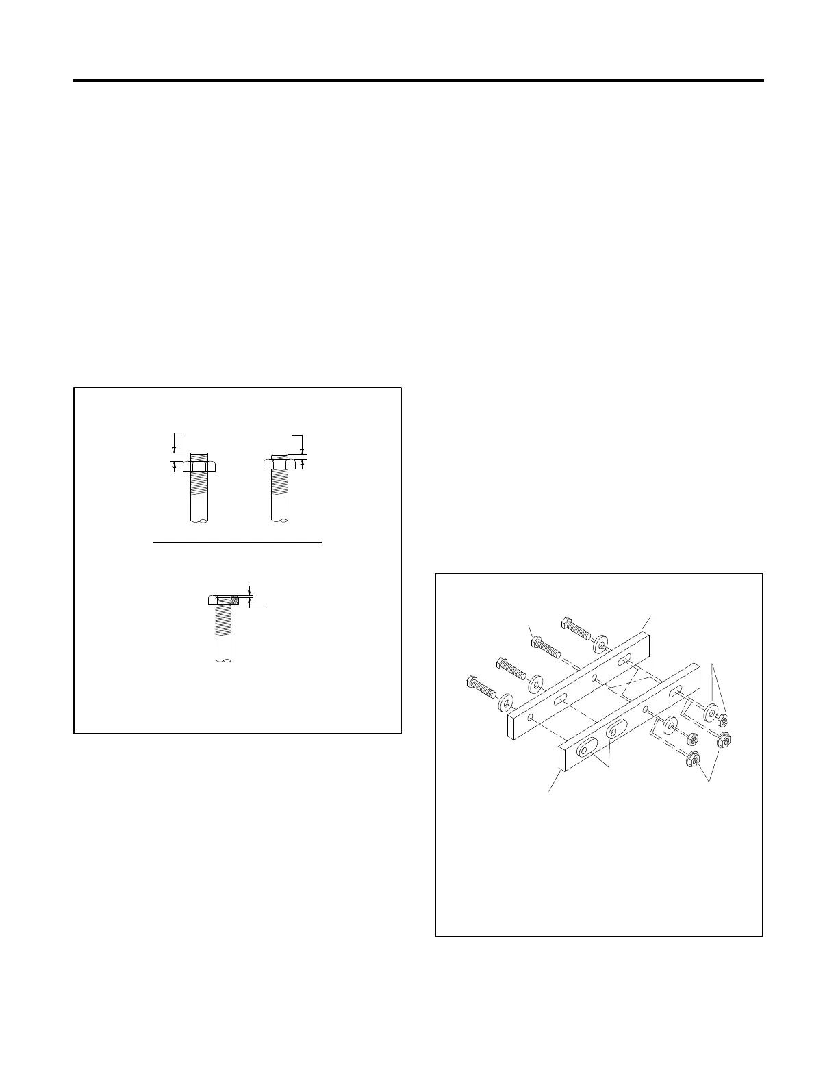
Steps for common hardware application:
1. Determine entry hole type: round or slotted.
2. Determine exit hole type: fixed female thread (weld
nut), round, or slotted.
For round and slotted exit holes, determine if
hardware is greater than 1/2 inch in diameter, or
1/2 inch in diameter or less. Hardware that is
greater than 1/2 inch in diameter takes a standard
nut and SAE washer. Hardware 1/2 inch or less in
diameter can take a properly torqued whiz nut or
spiralock nut. See Figure 2.
3. Follow these SAE washer rules after determining
exit hole type:
a. Always use a washer between hardware and a
slot.
b. Always use a washer under a nut (see 2 above
for exception).
c. Use a washer under a bolt when the female
thread is fixed (weld nut).
4. Refer to Figure 2, which depicts the preceding
hardware configuration possibilities.
G--585
1
2
3
4
5
6
1. Cap screw
2. Entry hole types
3. Standard nut and SAE washer
4. Whiz nut or spiralock: up to 1/2 in. dia. hardware
5. Weld nuts: above 1/2 in. dia. hardware
6. Exit hole types
Figure 2 Acceptable Hardware Combinations
 Loading...


