5
TT-1651 4/17a
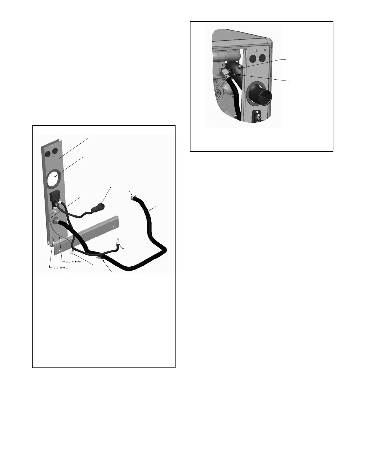
2.6 Ground lead connection. Connect the lead
(LK-0616-1715) to the ground stud located inside
the junction box using nut (M6923-06-80), washer
(M125A-06-80), lock washer (X-22-12 qty. 2), and
screw (M933-06020-60). Route the lead under the
U-channel shown in Figure 6. Connect the other
end of the lead to the customer connection panel
location. See Figure 9.
2.7 Fuel line connections. See Figure 9 for fuel
supply and return connection locations.
2.8 Secure the U-channel (X-6047-14) as shown in
Figure 6.
1. Customer connestion panel (GM93558 or GM95124)
2. Opening for exhaust tube.
3. Lead (LK-0616-1715).
4. Battery cable (X-545-259). Attach positive battery cable to
the starter motor.
5. Hose clamps (X-426-12 qty. 2). Attach seawater inlet hose to
inlet on the seawater pump.
6. Hose (X-373-30)
7. Battery cable (X-545-241 or X-545-176). Attach negative
battery cable to the engine block.
8. Insulated clamp (X-672-32)
9. Attach lead to the ground stud located inside of the junction
box using nut (M6923-06-80), washer (M125A-06-80),
lock washer (X-22-12 qty. 2), and screw (M933-06020-60).
GM93548-J
3
4
5
6
7
2
9
1
8
Figure 9 Customer Connection Panel Connections
GM93548-J
1. New location for existing hose connector
2. Route harness (GM96427) from temperature sensor to engine
harness.
1
2
Figure 10 New Location for Existing Hose Connector
 Loading...


