147Section 8 Decision-Makerr 3500 ControllerTP-6953 7/19
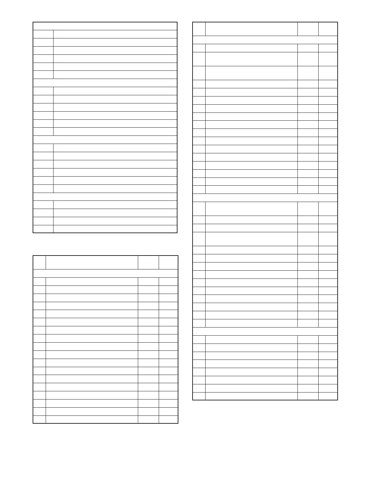
Analog Resistive Input
A1 Oil Pressure (Resistive Sensor 1)
A2 Coolant Temperature (Resistive Sensor 2)
A3 Lloyd’s Oil Pressure 2 (Resistive Sensor 3)
A4 High Exhaust Temperature (Resistive Sensor 4)
A5 Unused (Resistive Sensor 5)
A6 Unused (Resistive Sensor 6)
Analog Differential Input
V1P Circuit Breaker Status P (Diff. Volt Input 1P) *
V1N Circuit Breaker Status N (Diff. Volt Input 1N)
V2P Voltage Bias P (Diff. Volt Input 2P) *
V2N Voltage Bias N (Diff. V olt Input 2N)
V3P Speed Bias P (Diff. Volt Input 3P) *
V3N Speed Bias N (Diff. Volt Input 3N)
Digital Input
D1 Optional Low Coolant Level (D igital Input 1)
D2 Optional Low Oil Level (Digital Input 2)
D3 Optional Fuel Leak (Digital Input 3)
D4 Lloyd’s High Oil Temperature (Digital Input 4)
D5 Low Seawater Pressure (Digital Input 5)
D6 Lloyd’s Low Coolant Pressure (Digital Input 6)
Relay Driver Output
RDO1 Circuit Breaker Open (RDO1) *
RDO2 Circuit Breaker Close (RDO2) *
RDO3 RDO3 Cold Start
RDO4 RDO4 Relay Output
* Used for Paralleling
Figure 8 -2 User Inputs/Factory-Reserved Inputs
Pin
No.
Analog Digital
P1 Main Connector (35-Pin)
18 Oil Pressure (Resistive Sensor 1) (wire 7) A1
30 Coolant Temp (Resistive Sensor 2) (wire 5) A2
7 Speed Pickup (+) (BLU)
8 Speed Pickup (- ) (GRN)
15 Remote Start/Stop (wire 3)
14 E-Stop (wire 1)
26 E-Stop (wire 1A)
34 Digital Input 1 (wire 31) D1
25 Unused
22 Digital Input 2 (wire 25) D2
29 Current Sense CT_l1_P
17 CT_l2_P
28 CT_l3_P
16 CT_lR_N CT Return
27 Aux Shutdown / EOV (Marathon alternator)
33 Digital Input 3 (wire 64) D3
2 Unused
24 Controller Power (wire P1) (Battery +)
Pin
No.
Analog Digital
(Continued) P1 Main Connector (35-Pin)
3 Controller Ground (wire N4) (Battery - )
21 Digital Input 4 (Lloyd’s High Oil Temp)
(wire 69)
D4
31 Return (Analog) Isolated Ground
(wire BGA)
20 Unused
11 COM (- ) Isolated RS485
12 COM (+) Isolated RS485
23 PGEN (- )
35 PGEN (+)
9 Isolated CAN (+) (CAN 2) (yellow)
10 Isolated CAN (- ) (CAN 2) ( green)
5 NonIsolatedCAN(+)(CAN1)(yellow)
6 Non Isolated CAN (- )(CAN 1) (green)
13 Run (Battery +) (wire 70)
32 Digital Input 5 (Low Seawater Pressure) D5
19 Resistive Sensor 3 (Lloyd’s Oil Pressure 2) A3
4 Alternator Excitation Output (wire 38)
1 Crank Output (line 71)
P2 Options Connector (14-Pin)
12 Resistive Sensor 4 (High Exhaust
Temperature)
A4
11 Unused A5
10 Unused A6
1 Digital Input 6 (Lloyd’s Low Coolant
Pressure)
D6
2 Diff Volt Input 1P (CB Status*) BSP V1P
6 Diff Volt Input 1N (CB Status*) BSN V1N
3 Diff Volt Input 2P (Voltage Bias*) VBP V2P
7 Diff Volt Input 2N (Voltage Bias*) VBN V2N
4 Diff Volt Input 3P (Speed Bias*) SBP V3P
8 Diff Volt Input 3N (Speed Bias*) SBN V3N
5 RDO1 ( CB Open*) CBO RDO1
14 RDO3 (Cold Start) N7 RDO3
9 RDO2 (CB Close*) CBC RDO2
13 RDO4 (Relay Output) RD3 RDO4
P3 AC Sensing Connector (7-Pin)
7 Bus Voltage Sensing* - L1
8 Bus Voltage Sensing* - L2
4 Bus Voltage Sensing* - L3
5 Gen Voltage Sensing - L3 (C)
2 Gen Voltage Sensing - L2 (B)
1 Gen Voltage Sensing - L1 (A)
6 Gen Voltage Sensing - L0 (NEU)
3 Unused
* Used for Paralleling
Figure 8-3 Connector (P1, P2, & P3) Designations
 Loading...


