TP-6953 7/19 159Section 9 Component Testing and Adjustment
9.7.3 Switch Testing
Before testing switch, disconnect the switch lead(s).
Pressure Switch
Some pressure switches make contact on falling
pressure and some on rising pressure; refer to the
respective drawing for contact style. Connect an
ohmmeter to the switch terminals. Switches with one
terminal require connection to ground on the switch
metal body. Apply the pressure value shown in
Section 1 and observe the ohmmeter before a nd after
values to determine if the switch contacts open and
close per specifications.
Temperature Switch
High water temperature switches make contact on rising
temperature. Low water temperature switches make
contact on falling temperature. Refer to the respective
drawing for contact style. Connect an ohmmeter to the
switch terminals. Switches with one terminal require
connection to ground on the switch metal body. Apply
the temperature value shown in Section 1 and observe
the ohmmeter before and after values to determine if the
switch contacts open and close per specifications.
9.7.4 Sender Testing
Before testing sender, disconnect the sender lead(s).
Pressure Sender
Pressure senders change resistance values as
pressure changes. Connect an ohmmeter to the sender
terminals. Senders with one terminal require
connection to ground on the switch metal body. Apply
pressure values shown in Section 1 and observe the
ohmmeter values to determine if the sender changes
resistance per specifications.
Temperature Sender
Temperature senders change resistance values as
temperature changes. Connect an ohmmeter to the
sender terminals. Senders with one terminal require
connection to ground on the switch metal body. Apply
temperature values shown in Section 1 and observe the
ohmmeter values to determine if the sender changes
resistance per specifications.
9.7.5 Oil Pressu re Sender (OPS)
Testing
Disconnect the oil pressure sender lead 7. See
Figure 9-9. Check the sender resistance with an
ohmmeter. Compare the resistance values when the
generator set is shut down and when it is running at
operating temperature to the values shown in Section 1,
Specifications.
Use a mechanical oil pressure gauge to further verify
correct readings.
TP-5353-7
Lead 7
Figure 9-9 Oil Pressure Sender, Typical
9.7.6 Coolant Temperature Sender
(CTS) Testing
Note: For 32/40EKOZD and 28/35EFKOZD models,
consult the Engine Service Manual for CTS
testing. See the List of Related Literature found
at the beginning of this manual for the publication
number.
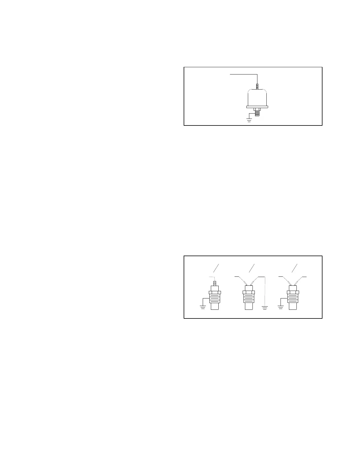
The coolant temperature sender has three
configurations: (1) a single function, single-terminal
type, (2) a single function, two-terminal type, and (3) a
dual function, two -terminal type with temperature
sender and low coolant temperature switch. See
Figure 9-10.
TP-5353-7
Lead 5
55
N
35A
Type 1 Type 2 Type 3
Figure 9-10 Coolant Temperature Sender, Typical
Sender type 3 has lead 5 connected to coolant
temperature sender terminal with a 6-32 screw and
lead 35A connected to the low water coolant
temperatureswitchterminalwithan8-32screw.
Disconnect the coolant temperature sender lead 5 (and
lead N with t ype 2 configurations). Check the sender
resistances with an ohmmeter. Compare the resistance
values when the generator set is shut down and when it
is running at operating temperature to the values listed
in Section 1, Specifications.
 Loading...


