TP-6953 7/19188 Section 11 Alternator Component Testing and Adjustment
LED OPTIC
BOARD
FRX ACTIVATOR
BOARD
MAGNETS
MAGNETS
EXCITER ARMATURE
ROTOR ASSEMBLY
FIELD WINDING
12 LEAD STATOR
ASSEMBLY
BATTERY
-
+
STARTER
P
S
P
CONTROL RELAY
CONTACTS
7N
70
12
11
10
9
8
7
6
5
4
3
2
1
AC1
FP
FN
AC2
SOLENOID
TP-6783-3
GENERATOR SET
CONTROLLER WITH
INTEGRATED VOLTAGE
REGULATOR
V7 V8 V9
AC3
P6
CONNECTOR
5B 3B
D1
V0
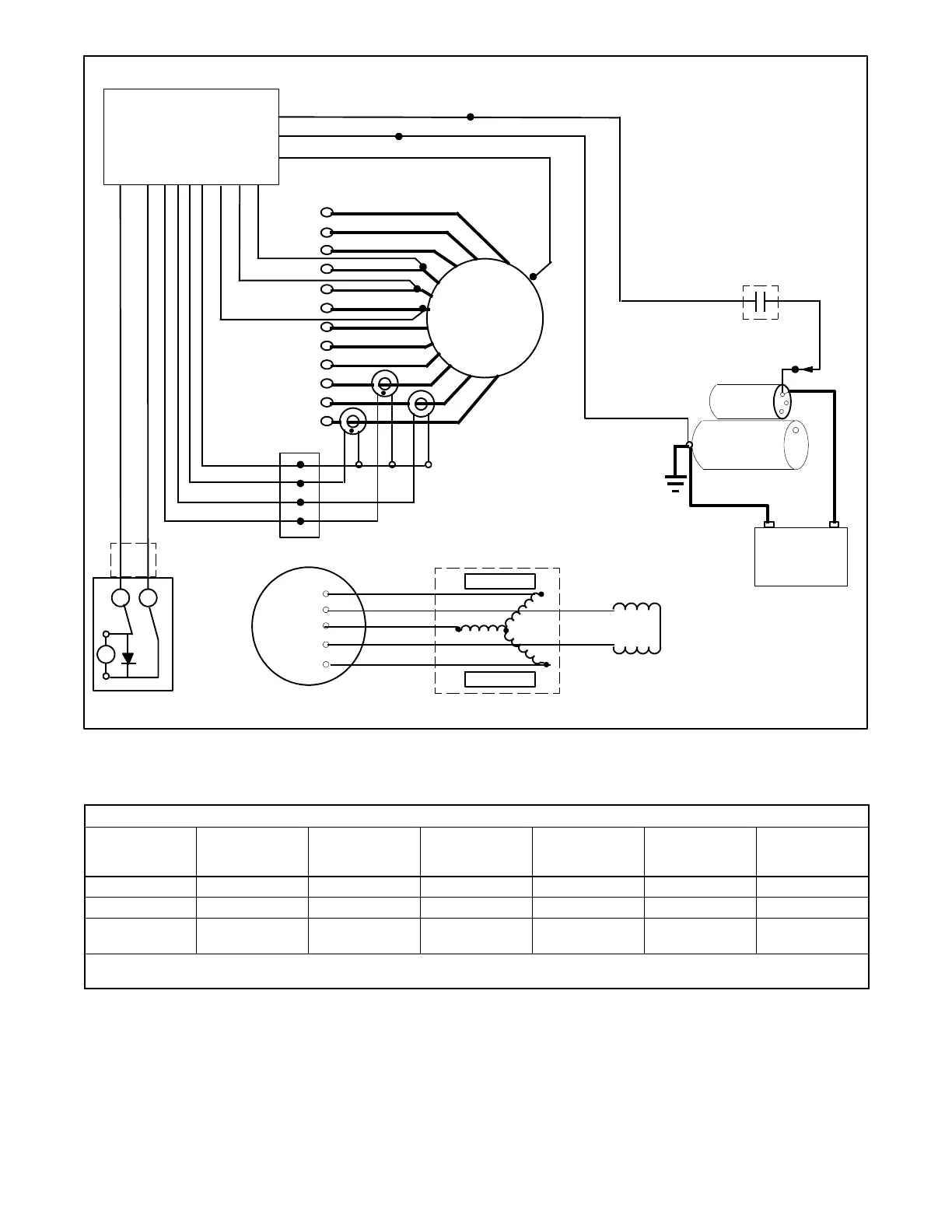
Figure 11 -1 AC Voltage Control Components
Components and Circuits to Test Under Certain Alternator Output Conditions
Alternator
Output
Condition
Controller with
Voltage
Regulator [
LED Optic Board
FRX Activator
Board
Exciter
Armature
Rotor Assembly
Field Winding
Stator Assembly
Windings
No Output
D D D D D D
Overvoltage
D D *
Fluctuating
Voltage
D D D D D D
* Overvoltage will occur if an outside light source is present when the LED board is removed.
[ See the operation or service manual for operation, setup, and/or troubleshooting.
Figure 11 -2 Alternator Assembly Troubleshooting Guide
 Loading...


