TP-6907 5/1694 Section 7 Disassembly/Reassembly
7.4 Connection Box Disassembly
Remove the connection box before removing the
alternator. Refer to Figure 7-2 and the schematic
diagrams, Section 8.
Note: To simplify the disassembly, the generator wire
harness and the connection box can be removed
together.
1. Be sure to perform the initial steps described in
Section 7.2 before p roceeding.
2. To remove the controller:
a. Remove the controller mounting bolts.
b. Lift the controller carefully and disconnect the
wire harness plugs and ethernet plug on the
back of the controller.
c. Remove the controller.
3. Remove the upper and lower access covers.
4. Label and disconnect the following alternator
harness leads inside the connection box:
D Auxiliary power, exciter field leads and voltage
sensing leads
D Alternator leads on the circuit breaker
5. Label and disconnect the following leads inside the
connection box:
D Load leads on the circuit breaker
D External leads on TB1 such as the transfer
switch or load control module connections
D 120 V utility power leads for the battery charger
6. Open the saddle box lid on the alternator and pull
the alternator leads out of the connection box.
7. Label and disconnect the following generator wire
harness connections as needed on the radiator
and the engine compartment:
D Engine harness connector
D Coolant level sensor, located at the top of the
radiator. See Figure 7-3.
D Radiator fans
D Engine compartment fan
D Engine compartment temperature sensor
D Quick connection leads on the ballast resistor.
The ballast resistor is located on the alternator
saddlebox. Remove the cover to access the
ballast resistor connections.
D Quick connection leads on the fuel solenoid
valves
D Generator wire harness leads connected to the
starter motor
8. Remove the connection box ground strap that
connects to the skid.
9. Remove four mounting bolts at the base of the
connection box.
10. Move the connection box out of the way and
remove the g round on the stator housing.
11. Carefully lift the connection box off the skid.
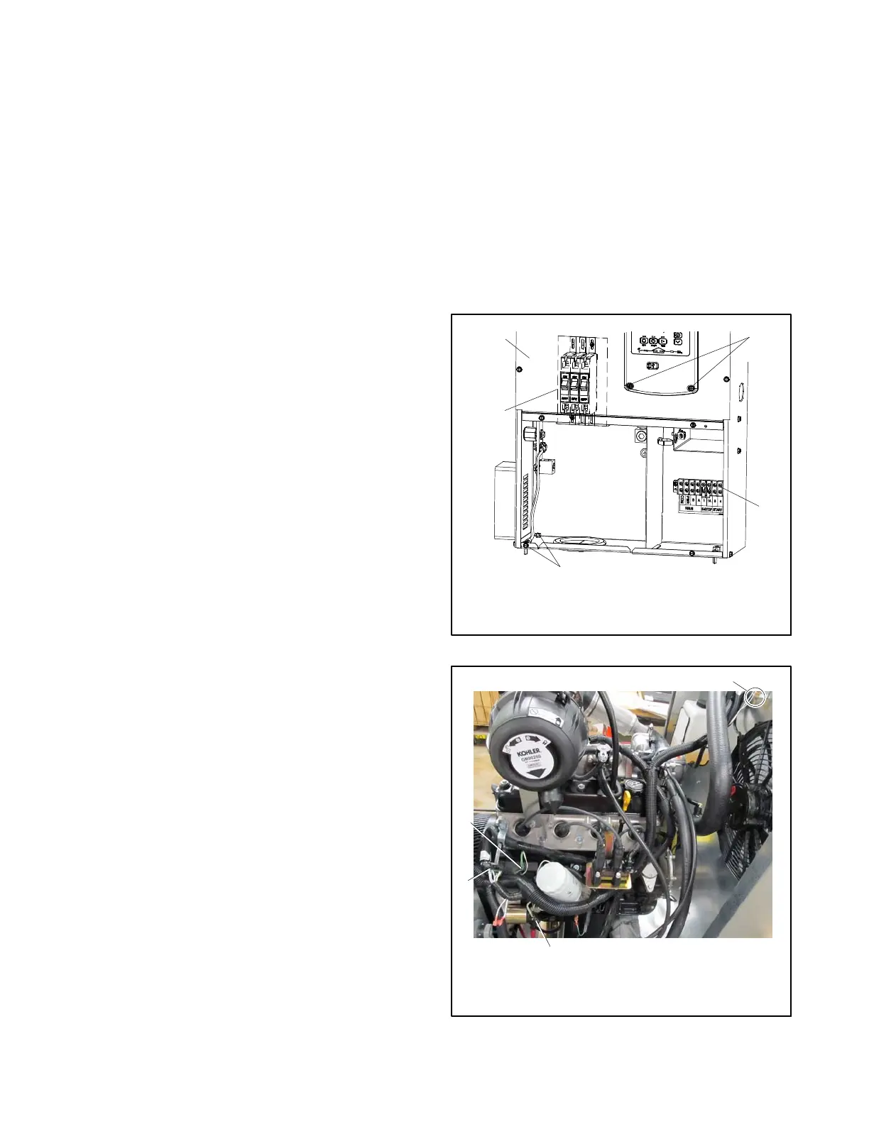
1. Connection box
2. Controller mounting
bolts
3. TB1
4. Mounting bolts, qty. 4
5. Circuit breaker
4
1
5
2
3
Lower access panel removed.
Figure 7-2 Connection box
558866
1. Coolant level sensor
2. Starter motor
3. ECM interface
4. Leads and battery
grounds
3
2
1
4
Figure 7-3 Wire Harness Connections
 Loading...


