TP-6197 3/0632 Section 4 Troubleshooting
4.3 Circuit Protection
If the generator set circuit breaker trips or the fuses blow
repeatedly, see Section 4, Troubleshooting, for possible
causes.
4.3.1 Line Circuit Breaker
A line circuit breaker interrupts the generator output in
the event of a fault in the wiring between the generator
and the load. The line circuit breaker location is shown
in Figure 1-1. If the circuit breaker trips, reduce the load
and switch the breaker back to the ON position.
4.3.2 Fuses
The engine harness contains three 10-amp inline fuses.
Four additional fuses are located inside the junction box.
See the service views in Section 1 for the fuse locations
and Figure 4-2 for replacement fuse part numbers.
Always identify and correct the cause of a blown fuse
before restarting the generator set. Refer to s ection 4,
Troubleshooting, for conditions that may indicate a
blown fuse. Obtain service from an authorized
distributor/dealer.
F1 Auxiliary Winding Fuse. A replaceable 10-amp
fuse protects the alternator.
F2 Relay Fuse. A replaceable 10-amp fuse protects the
engine relays. If the generator set does not crank, check
the battery and battery connections and then check the
relay fuse.
F3 Controller Fuse. A replaceable 10-amp fuse
protects the controller circuitry. If the controller display is
dark, check the battery and battery connections and
then check the controller fuse.
F4--F7 Engine Fuses. See Figure 4-2 and the wiring
diagrams.
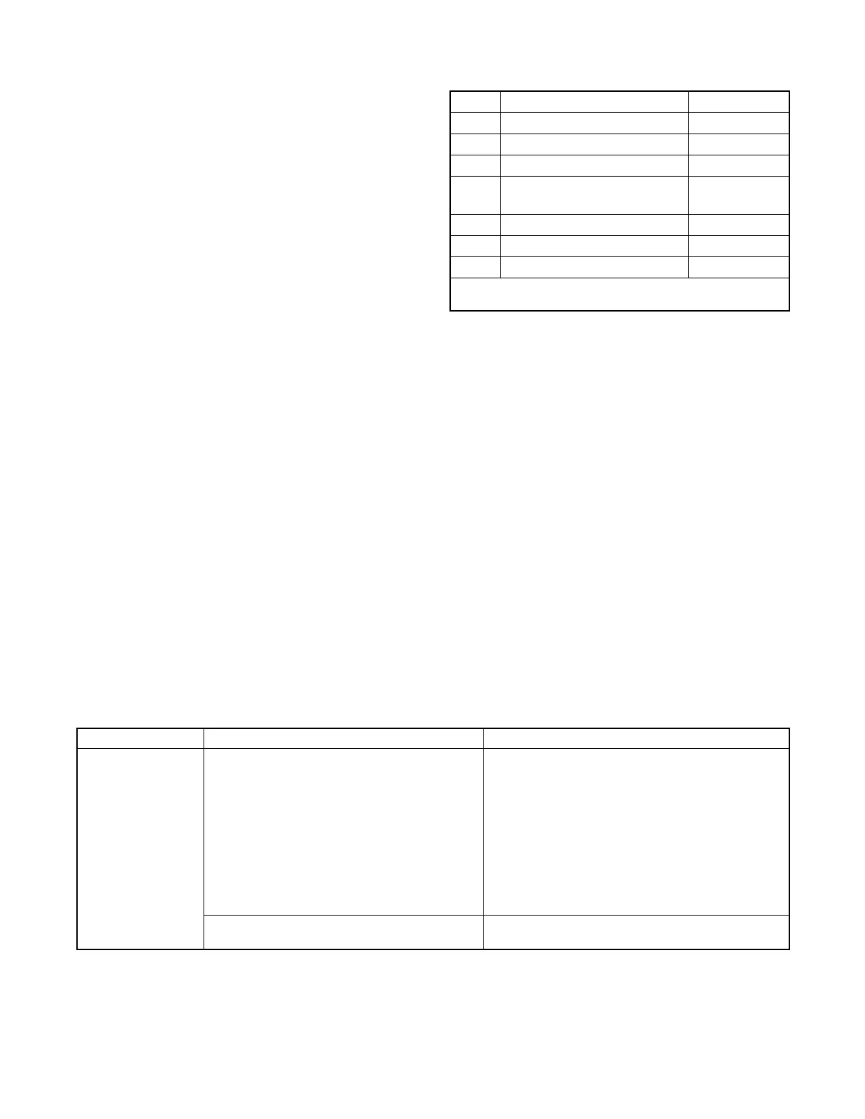
Fuse Description Part Number
F1 10 Amp Auxiliary Winding 358337
F2 10 Amp Relay Interface Board 223316
F3 10 Amp Controller 223316
F4
15 Amp Battery Charging
Alternator
283645
F5 * N/A * N/A *
F6 20 Amp Main Power Relay GM39266
F7 5 Amp ECM Power, Switched 239298
* The F5 fuse is not used on the models covered by this
document.
Figure 4-2 Fuses
4.4 Fault Codes
The Advanced Digital Control displays fault codes to aid
in troubleshooting. Fault codes, descriptions, and
recommended checks are listed in Figure 2-4.
Identify and correct the cause of the fault condition.
Then reset the controller after a fault shutdown. See
Section 2.3.5.
4.5 Troubleshooting
Figure 4-3 contains troubleshooting, diagnostic, and
repair information for the Advanced Digital Control.
Problem Possible Cause Corrective Action
Controller LED
displayisoff
No power to the controller:
Continuous power mode jumper is
disconnected and the generator set has not
run for 48 hours or longer.
Controller display will automatically activate when a
remote start command is received or the generator
set master switch is moved to the RUN position.
See Section 2.3.6. Connect the jumper to maintain
continuous power to the controller, if desired.
Controller fuse (F3) is blown. Replace the fuse. If the fuse blows again, contact
the distributor/dealer.
Low or no battery voltage. Check connections.
Check generator set battery. See Figure 4-1.
Generator set master switch is in the
OFF/RESET position.
Move generator set master switch to the AUTO or
RUN position.
Figure 4-3 ADC 2100 Troubleshooting Chart
 Loading...

