TP-6391 9/08 21Section 3 Troubleshooting
Troubleshooting Chart, continued
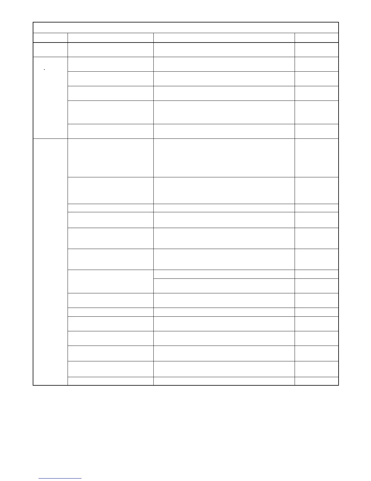
Problem ReferenceCorrective ActionPossible Cause
Light
flicker
Voltage stability (gain) setting Check and adjust the voltage stability (gain) setting
using the ADC 2100.
Section 5.7
High
output
Incorrect controller configuration Check and adjust the controller configuration
parameters.
Section 4.11.2
voltage
Incorrect controller voltage
settings
Check and adjust the controller voltage settings. Section 5.7
Loose voltage sensing
connections
Check connections: stator leads 11 and 44 and P15
controller connection.
Section 7
SCR module Check wiring and connections to the SCR module.
Check auxiliary winding fuse F1 (lead 55).
Replace SCR module and recheck voltage.
Section 4.9
Section 5.12
Section 4.9
Controller Check fuses, wiring and connections. Before replacing
controller, replace SCR module and test voltage.
Section 4.10
No output
voltage
AC output circuit breaker open Check for AC voltage on the generator side of circuit
breaker. If there is AC voltage on the generator side of
the breaker, then a problem in the l oad circuits is
causing the line circuit breaker to trip. Check for and
correct short circuits or overloading on the load side
before resetting the circuit breaker.
—
Alternator or control system Perform separate excitation procedure to isolate the
problem to the alternator or the control system. Then
troubleshoot the alternator or control system
components as follows.
Section 5.2
Aux. winding F1 fuse blown Replace blown fuse. If fuse blows again, check stator. Section 5.3
SCR module Check auxiliary winding fuse F1 (lead 55).
Replace SCR module and test voltage.
Section 5.12
Section 4.9
Controller Check controller settings. Check wiring and
connections. Before replacing controller, replace S CR
module and check voltage.
Section 4.11.2
Section 4.10
Open wiring, terminal, or pin in
buildup circuit or SCR module
circuit
Check continuity. Section 5.13
Section 7
Brushes
Inspect brushes and replace if worn. Section 5.6
Check for brushes sticking in brush holder or broken
brush spring.
Section 5.6
Rotor connections Check for open circuit in rotor connection circuit (leads
FN and FP to SCR and RIB).
Section 7
Rotor slip rings dirty or corroded Check slip ring condition. Section 5.4
Rotor (open, grounded, or
shorted windings)
Check voltage and continuity. Section 5.4
Stator (open, grounded, or
shorted windings)
Check voltage and continuity. Section 5.3
Flash relay (K3) on relay
interface board (RIB)
Check flash LED on RIB.
Check fuse F2 and troubleshoot RIB.
Section 4.6
BlownF2fuse Replace fuse If fuse blows again, check circuit and
components.
Section 5.12
Section 7
BlownF5fuse Check ECM ground connection pin 14. Section 7
 Loading...

