TP-6391 9/08 33Section 4 Controller
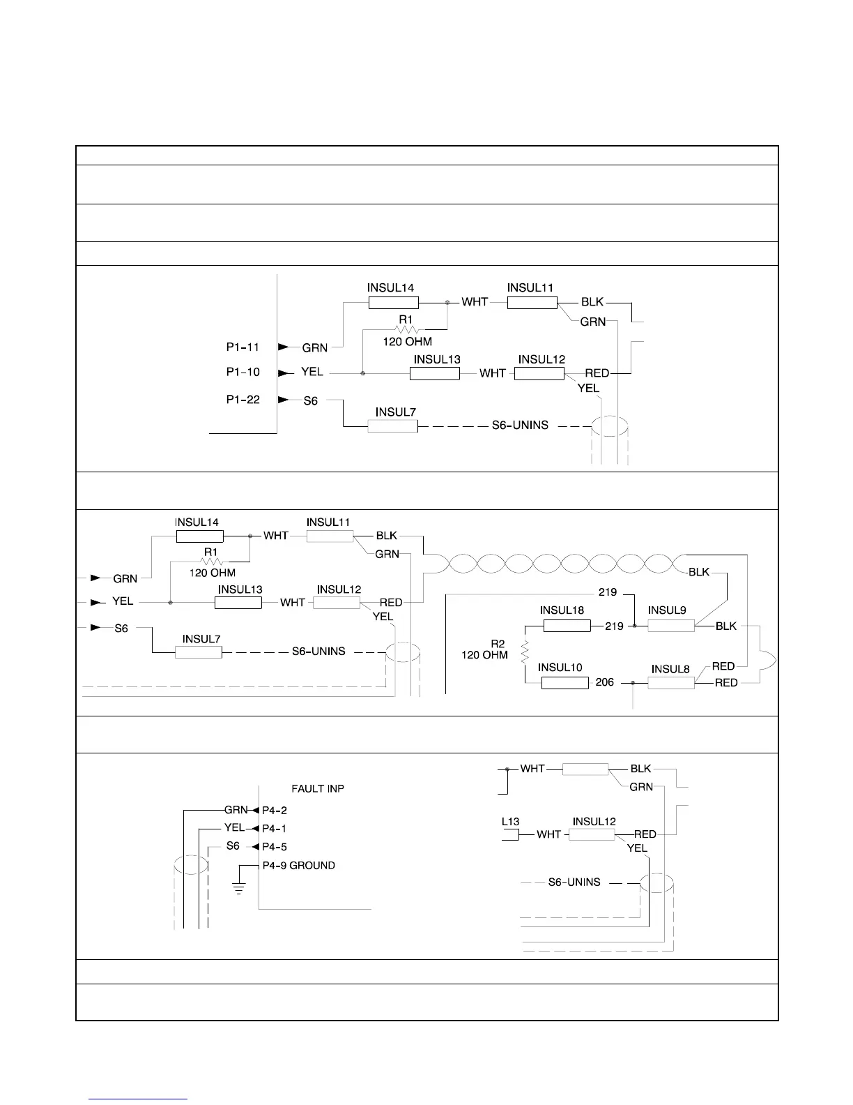
Note: Generator sets built after serial number 2175814 have a different engine harness design. For serial numbers
after 2175814, the communication wires are green and yellow. Pin locations remain the same. Resistors are
removable.
Note: For complete wiring diagram details, see Section 7.
Verify Control Area Network (CAN) Resistance
Disconnect the ADC 2100 control plug (P1), ECM (P10), remote12-pin customer interface (P4), and SmartCraftt
communications plug (P19).
Measure the resistance at the P1 (ADC) connector pins 11 and 10 (YEL and GRN labeled wires). The meter should indicate
60 ohms.
If the meter reads 0 ohms, there’s an open circuit between the pins to the R1 resistor.
If the meter reads 120 ohms, the t wo resistors in the harness are no longer in parallel. Check the connections between the
resistors.
Verify a resistance of 60 ohms at the P4 (customer interconnect) connector, pins 1 and 2 (YEL and GRN). The meter should
read 60 ohms.
If the meter reads 0 ohms, there are open wires from the P4 connector to the Insul 14 and Insul 12.
If the meter reads 120 ohms, the t wo resistors in the harness are no longer in parallel. Check the connections between the
resistors.