TP-5393 9/93 Scheduled Maintenance 3-5
Ignition System
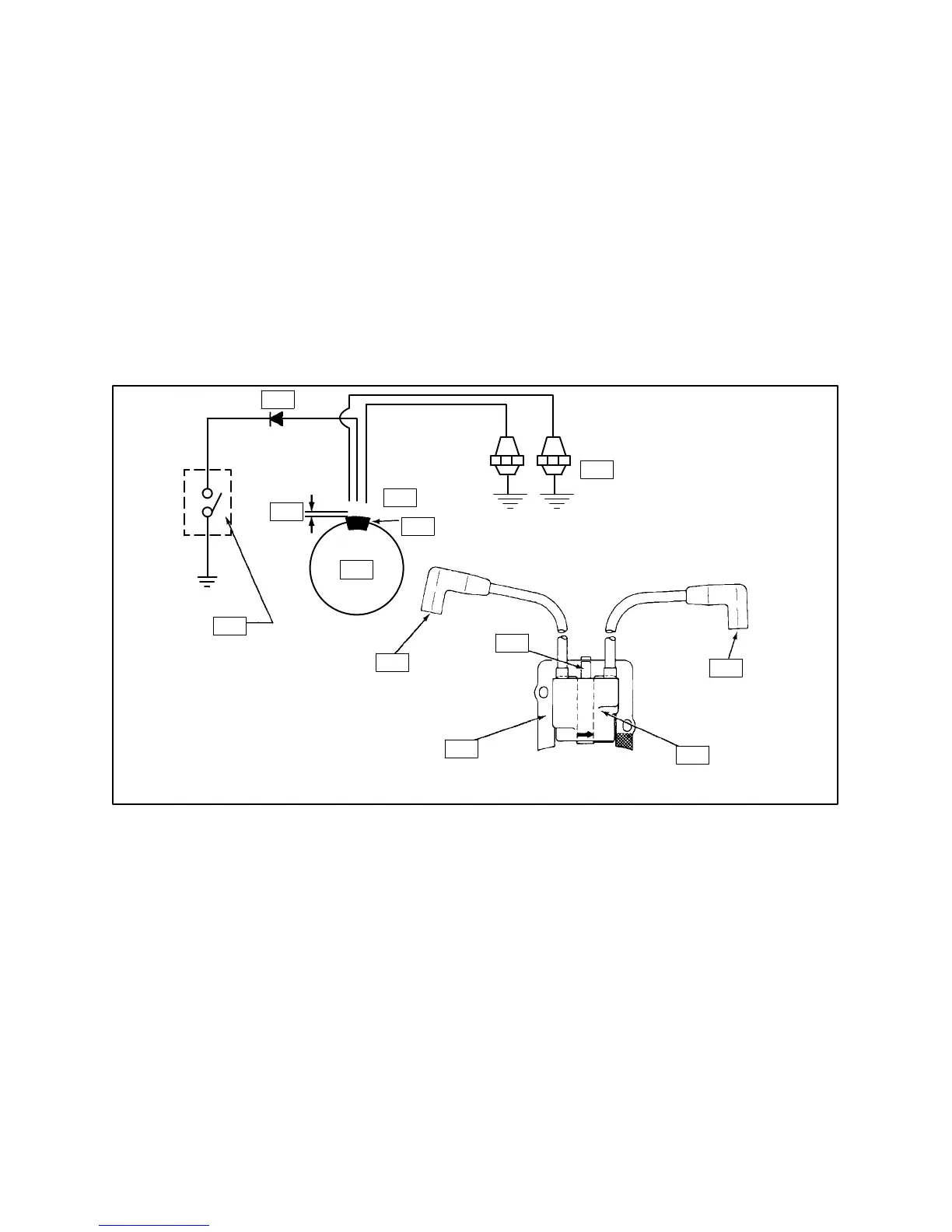
Electronic Magneto Ignition System
The 4 and 5 kW generator sets are equipped with a
dependable electronic magneto ignition system
(Figure 3-6) containing the following:
D A magnet assembly which is PERMANENTLY
affixed to the flywheel.
D An electronic magneto ignition module, which is
mounted to the #1 side cylinder barrel.
D A controller which stops the engine by grounding
the ignition module.
Operation
As the flywheel rotates and the magnet assembly
movespasttheignitionmodule,alowvoltage isinduced
in the primary windings of the module. When the
primary voltage is precisely at its peak, the module
induces a high voltage in its secondary windings. This
highvoltagecreates asparkatthetipofthesparkplugs,
ignitingthefuel-airmixtureinthe combustionchambers.
Other than periodically checking/replacing the spark
plugs, no maintenance, timing, or adjustments are
necessary with this ignition system.
1
2
3
4
5
6
7
8
9
10
11
12
Figure 3-6. Electronic Magneto Ignition System
1. Diode
2. 0.008/0.012” Air Gap
3. Ignition Module
4. Magnet
5. Spark Plugs
6. High Tension Lead (D)
7. Coil Assembly
8. Laminations (A)
9. Kill Terminal (B)
10. High Tension Lead (C)
11. Kill Switch or Off Position of Keyswitch
12. Flywheel
 Loading...

