6-14 Installation TP-5393 9/93
1
1
2
3
4
5
6
7
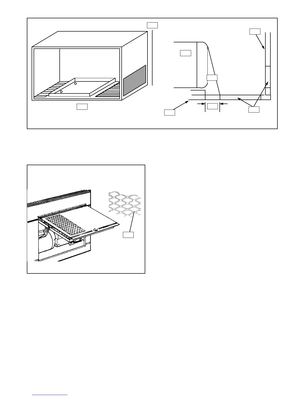
1. Generator end
2. 5°
3. End wall
4. Air inlet at floor or end wall
5. 1.22 in.
6. Compartment floor
7. Mounting tray must not cover any portion of air inlet/outlet
openings.
Figure 6-17. Floor or End Wall Air Inlets
1
1. Wide Mesh Screen
Figure 6-18. Inlet Screen/Louvers Restrict Air
Flow
If the air-intake opening is located in the compartment
floor or end wall, a space must remain between the
generator end and the compartment air opening. The
width of the space must be equal to a point on the
compartment floor 5° from the top of the generator.
(Typically, a distance of 1.22 in. on most 4 and 5 kW
generator installations.) See Figure 6-17. A fireproof
floor(flooringmadeofanon-combustiblematerial)must
also be installed between the mounting tray and
enclosure walls. These precautions are necessary to
prevent hot airfrom leavingthegeneratorcompartment
and igniting combustible material beneath the coach.
Remember, louvers, screens, and
protective-decorative grill work definitely restrict the
effective air flow. Even a simple, relatively open-mesh
screen as seen in Figure 6-18 will restrict air flow as
much as 45%. The intake opening must be increased to
compensate for such restrictions.
The remainder of this section covers installation
instructionsforboth RVand Mobile generatorsets.
 Loading...

