Do you have a question about the Kohler 5EOZ and is the answer not in the manual?
Precautions against unintended starting and hazards associated with batteries.
Risks from fire, exhaust fumes (carbon monoxide), and fuel vapors.
Dangers of hazardous noise, voltage, electrical shock, and proper grounding.
Precautions for handling hot components and avoiding injury from moving parts.
Description of the manual's scope, purpose, and product information.
Contact information for Kohler service assistance and distributors worldwide.
Details on generator set models and their corresponding engines.
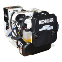
Visual identification of generator set components and their locations.
Technical data and performance parameters for the generator engines and generator.
Safety guidelines for maintenance and procedures for the lubrication system.
Guidelines for battery maintenance and preparing the generator for storage.
Service procedures for air intake filter and inspection of exhaust system components.
Cleaning and inspection of the exhaust mixing elbow for buildup.
Information on fuel system, fuel type, filter replacement, and bleeding procedures.
Testing and service procedures for fuel solenoid, pump, and governor adjustment.
Identification of cooling system parts and general safety checks.
Exhaust manifold details, coolant levels, and system flush procedures.
Maintenance for seawater pump impeller, pressure cap, belt tension, and siphon break.
Procedure for checking and replacing the anticorrosion zinc anode.
Using controller LEDs, sequence understanding, and safety shutdown switches.
Methods for testing circuit board components and diagnostic flowcharts.
Initial checks, fuse testing, and separate excitation procedure for output issues.
Procedures for testing voltage regulator, exciter, rectifier, rotor, and stator for faults.
Steps for safely taking apart the generator set components.
Guidelines for correctly reassembling the generator set after service.
Instructions for changing the generator set's voltage configuration.
Schematic, point-to-point diagrams, and transfer switch operation.
Appendices covering abbreviations, hardware guidelines, torque specs, and identification.
| Voltage | 120/240 V |
|---|---|
| Fuel Type | Gasoline |
| Rated Watts | 5000 W |
| Fuel Tank Capacity | 4.5 gallons |
| Outlet Types | 120/240 V 30 A Outlet |
| Noise Level | 68 dB at 23 feet |