TP-6391 9/0856 Section 5 Component Testing and Adjustment
Heated Oxygen (O
2
) Sensor
The heated oxygen sensor is used to monitor O
2
in the
exhaust. See Figure 5-22 for the heated oxygen sensor
location.
Note: The heated oxygen sensor is calibrated to work
with this system. Do not use alternate sensors.
The oxygen sensor operates like an electrolyte with its
platinum layers serving as electrodes. After the internal
element reaches approx. 600_ F, it becomes electrically
conductive and attracts negatively charged ions of
oxygen. These ions collect on the inner and outer
platinum surfaces.
A heated element is added to the sensor housing in
order for the sensor to conduct and create an electrical
signal below 600_ F. Two wires provide 12VDC and a
ground signal for the heater element. A fourth wire
provides an independent ground for the sensor. The
targeted air/fuel ratio signal is approx. 500mV and
changes slightly based on speed and load conditions.
When the sensor sends a voltage signal less than
500mV, the ECM interprets the air/fuel mixture as lean
so the ECM decreases the duty cycle. If the ECM
receives a voltage signal above 500mV, the air/fuel
mixture would be interpreted as too rich and the ECM
would increase the duty cycle.
Set the generator set master switch to the OFF position
and allow the generator set to cool. Disconnect the
heated oxygen sensor and use an ohmmeter to
measure the resistance across the sensor pins. See
Figure 5-21.
O
2
Sensor Pin Resistance Check
Pin C (HEATER GND) to
Pin D (HEATER PWR)
2.1 ¦ 0.4 Ohms
Figure 5-21 O
2
Sensor Resistance
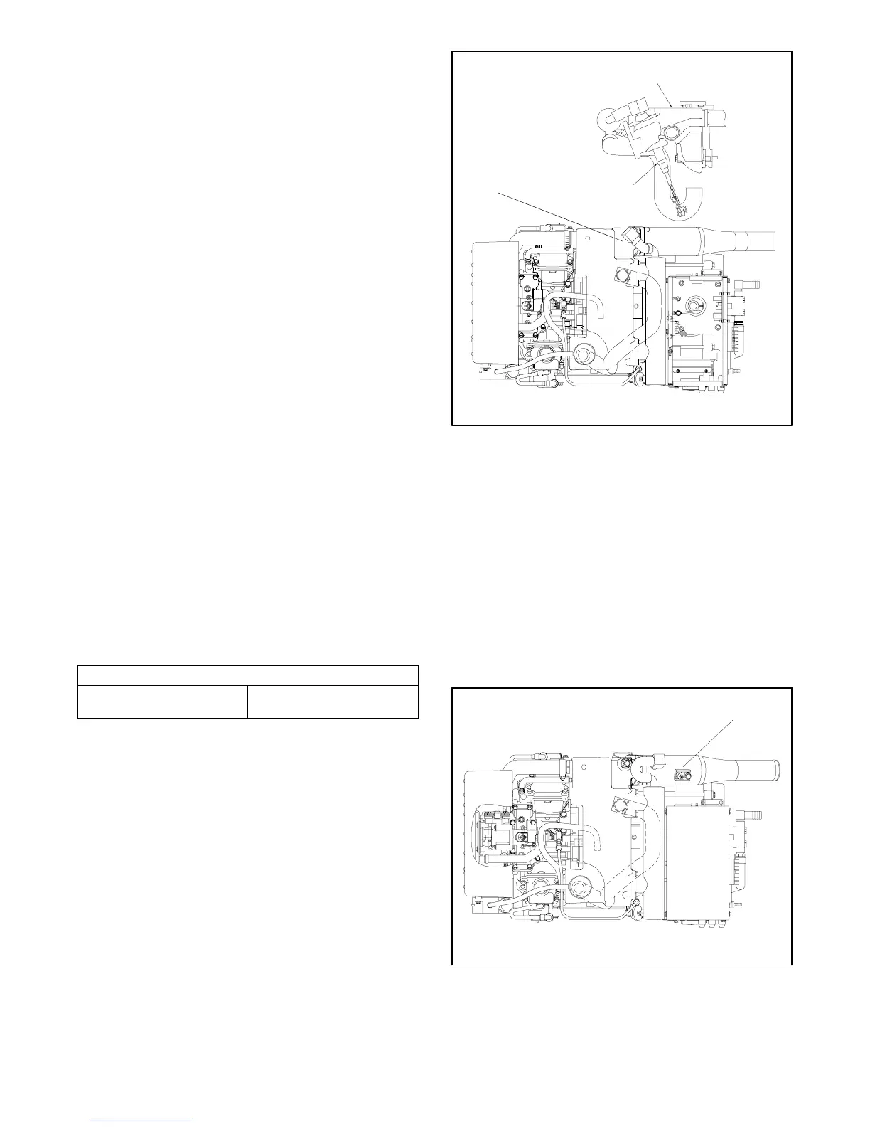
1
GM39685B-J
1. Heated oxygen sensor
2. Exhaust manifold
2
Top View
See Detail A
Detail A
Figure 5-22 Heated Oxygen Sensor Location
High Exhaust Temperature (HET) Switch
Note: The high exhaust temperature switch is installed
on units with serial numbers 2199434 and later.
In the event of a shutdown because of the high exhaust
temperature switch, the ADC 2100 controller will display
fault code LOC. See Figure 5-23 for the high exhaust
temperature switch location.
High exhaust temperature of 215_±5_F (102_±2.8_C)
will cause the unit to shut down.
Top View
1. High exhaust temperature switch
1
Figure 5-23 High Exhaust Temperature (HET) Switch
Location