2
TT-1583 9/13
Disabling the generator set. Accidental starting can
cause severe injury or death. Before working on the
generator set or connected equipment, disable the generator
set as follows: (1) Move the generator set master switch to the
OFF position. (2) Disconnect the power to the battery charger.
(3) Remove the battery cables, negative (--) lead first.
Reconnect the negative (--) lead last when reconnecting the
battery. Follow these precautions to prevent starting of the
generator set by an automatic transfer switch, remote
start/stop switch, or engine start command from a remote
computer.
Hazardous voltage.
Can cause severe injury or death.
Operate the generator set only when
all guards and electrical enclosures
areinplace.
Moving parts.
WARNING
Testing live electrical circuits. Hazardous voltage or
current can cause severe injury or death. Have trained and
qualified personnel take diagnostic measurements of live
circuits. Use adequately rated test equipment with electrically
insulated probes and follow the instructions of the test
equipment manufacturer when performing voltage tests.
Observe the following precautions when performing voltage
tests: (1) Remove all jewelry. (2) Stand on a dry, approved
electrically insulated mat. (3) Do not touch the enclosure or
components inside the enclosure. (4) Be prepared for the
system to operate automatically.
(600 volts and under)
Installation Procedure
1.1 Push the generator set power button OFF.
1.2 Disconnect power to the battery charger, if
equipped.
1.3 Disconnect the generator set engine starting
battery, negative (--) lead first.
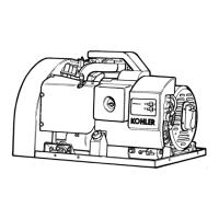
1.4 Using a 5/16 in. nut driver, loosen and remove the
four controller mounting screws securing the
controller and carefully lift the controller. See
Figure 3.
Note: Be careful of the leads and harness
connected to the controller.
1
GM58162-D
1. Controller mounting screws (4)
Figure 3 ADC IId Mounting Screws
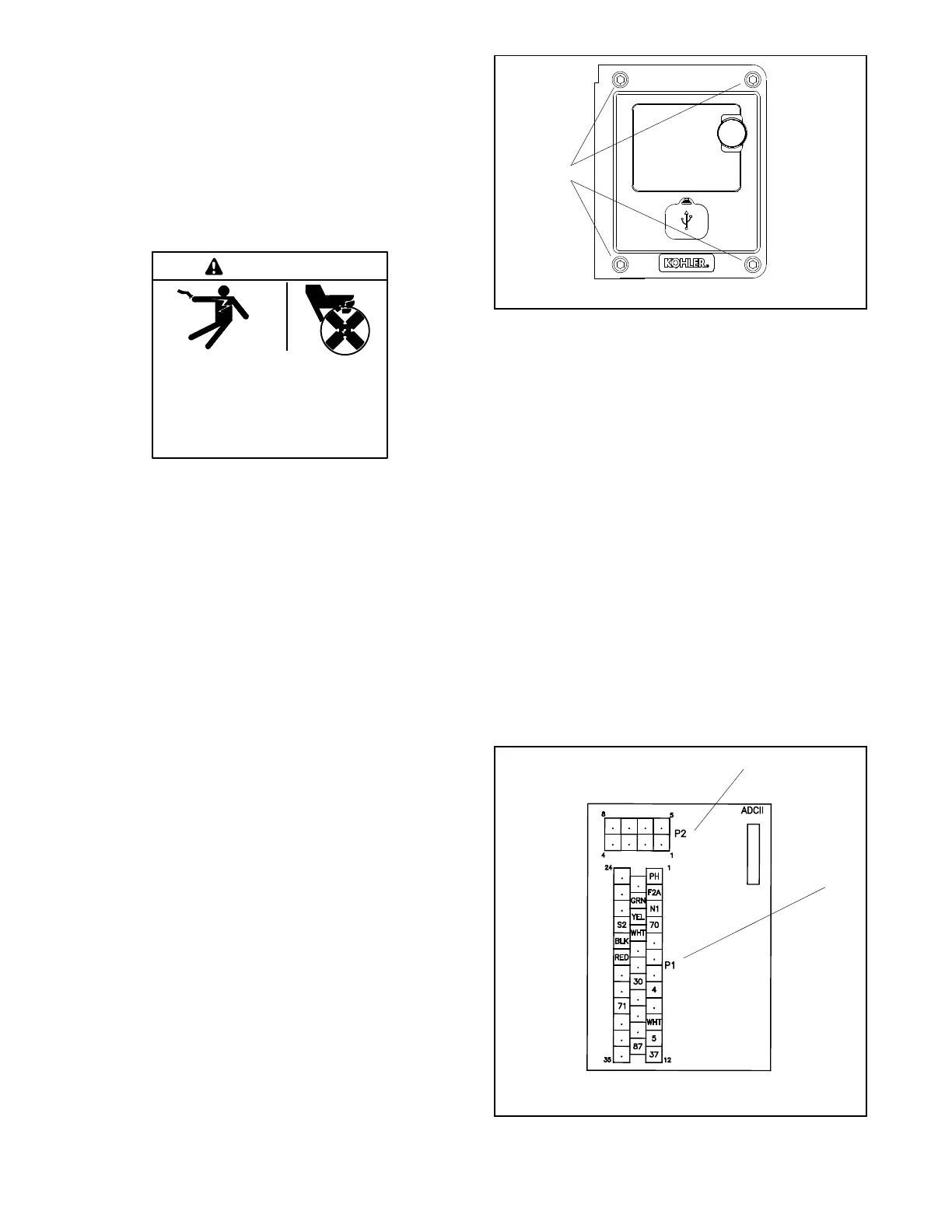
1.5 Note the connections on the back of the controller
and then disconnect wiring harness plugs P1
(35-pin plug) and P2 (8-pin plug) from the ADC IId.
SeeFigure4.
1.6 Remove the old controller.
Replace the Controller
1.7 Reconnect P1 (35-pin plug) and P2 (8-pin plug) to
the new controller assembly (GM82832).
1.8 Mount the new controller assembly onto the
junction box using the four (4) screws removed in
step 1.4.
1.9 Reconnect the engine starting battery, negative
(--) lead last.
1.10 Reconnect power to the battery charger, if
equipped.
1
GM79009-A
1. P1
2. P2
2
Figure 4 Controller Connections, Typical
 Loading...