8.17
Section 8
Electrical System and Components
8
NOTE: When removing the lever and armature
be careful not to lose the thrust washer.
8. The stop collar consists of two similar pieces held
in place by being snapped over a retainer. The
retainer is held in place by a groove in the
armature shaft. To remove the stop collar the
two pieces must be pried off the retainer.
9. When the stop collars are removed, the retainer
can be removed from the armature shaft. Electric
Starter Service Kit (see Section 2) includes a
special pliers for removing the retainer. Do not
reuse the retainer.
Brush Replacement
The brushes in the starter are part of the starter
frame. Brush kit Part No. 52 221 01-S contains four
replacement brushes and springs. If replacement is
necessary, all four brushes should be replaced.
1. Remove brushes from brush holder, and remove
brush holder from frame.
2. Cut the brush lead wire at the edge of the post
with a pair of nippers.
3. File off burrs on the post.
4. The replacement brushes have a solid portion on
them which should be crimped on the post.
5. Solder the crimped portion to the post.
6. Replace the brush holder in the frame and place
the brushes in the brush holder. Reinstall the
springs. Snap the insulator into the brush holder
to keep the springs from popping out.
Starter Service
Clean drive lever and armature shaft. Apply Kohler
electric starter drive lubricant (See Section 2) to lever
and shaft.
Starter Reassembly
1. Install the drive pinion onto the armature shaft.
2. Slide the stop collar onto the armature shaft
below the retaining ring groove. Make sure the
recessed side of the stop collar is up.
3. Position a new retainer in the groove of the
armature shaft, and carefully tighten with a
pliers to secure.
NOTE: Always use a new retainer. Do not nick
or damage armature shaft.
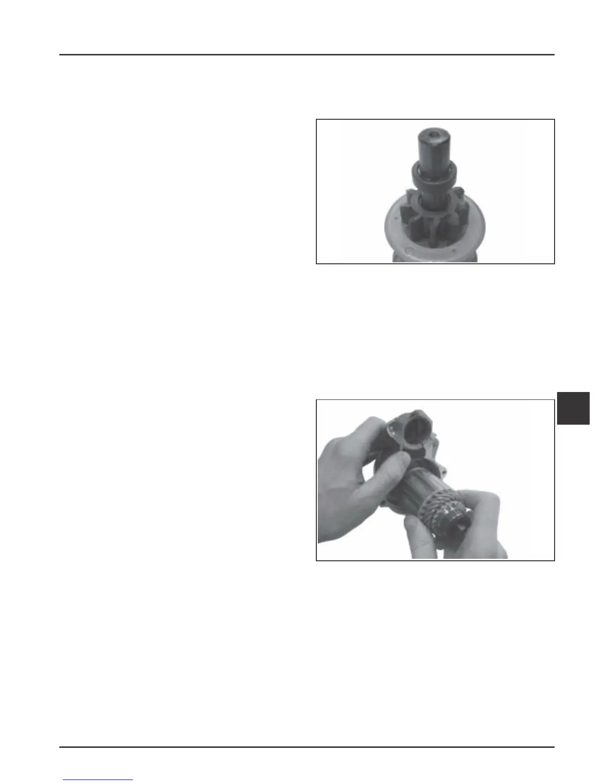
4. Use an open end wrench and slide the stop collar
up, until the recessed section encases the
retaining ring and locks the collar into position.
See Figure 8-20.
Figure 8-20. Lock Collar around Retaining Ring.
5. Install the thrust washer onto the armature shaft
and lightly lubricate the end of the shaft with
drive lubricant.
6. Position the lubricated drive lever around the
drive pinion assembly and insert the assembly
into the drive end cap. Seat the pivot section of
drive lever into the corresponding section within
the housing. See Figure 8-21.
Figure 8-21. Installing Armature.
7. Mount the brush holder to rear of starter frame.
Install the four brushes into the corresponding
slots. Then carefully work (set) each of the four
brush springs into position behind the brushes.
Slide the rubber insulating grommet onto the
small corresponding plastic tab on frame. See
Figure 8-22.
 Loading...