10.4
Section 10
Reassembly
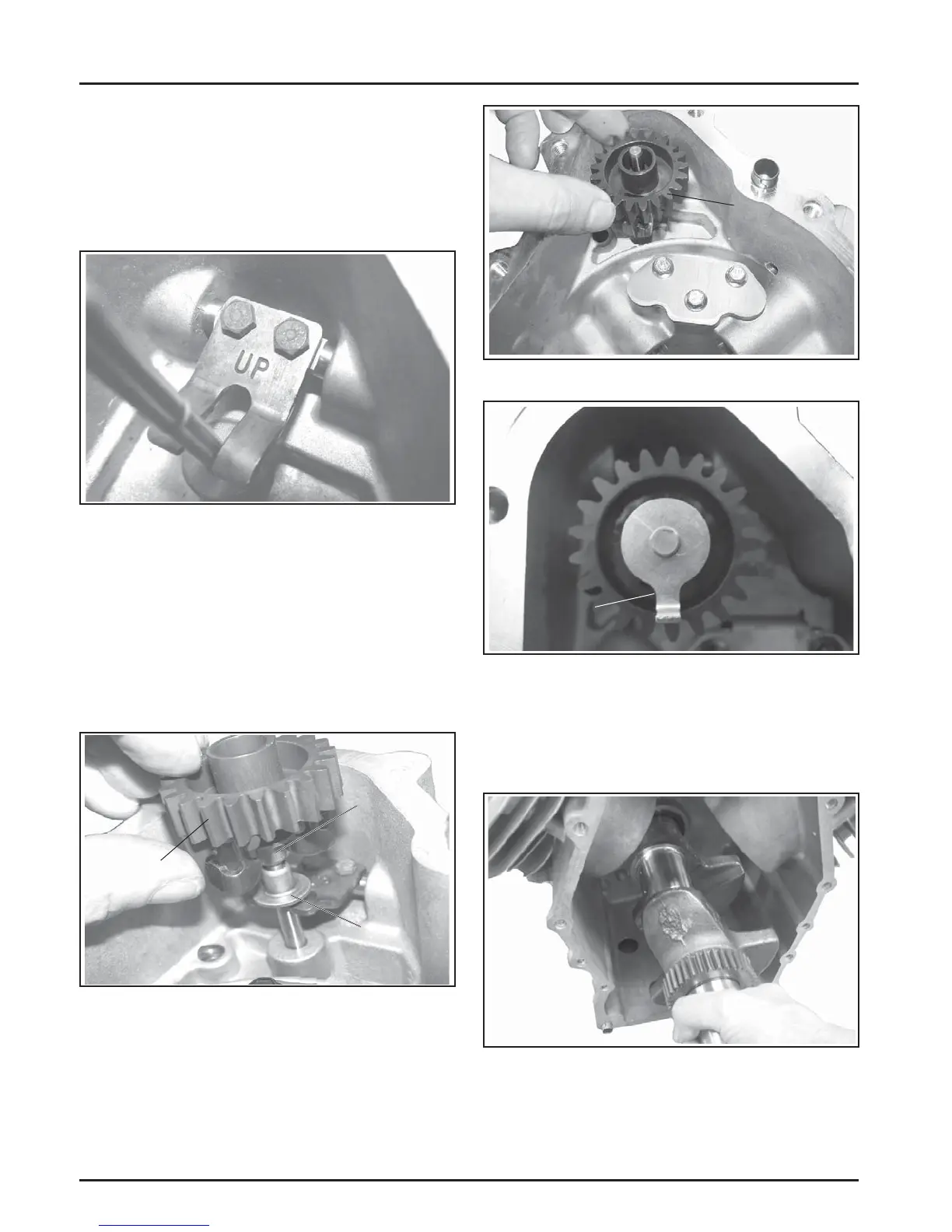
4. A ach the governor yoke to the cross sha so
the curved section is up as marked. Secure with
the two screws. If a thread locking compound is
not preapplied, apply a small amount of Loctite
®
266™ Threadlocker or equivalent, to the screw
threads before installing. Torque the screws to
2.2 N·m (20 in. lb.). See Figure 10-12.
Figure 10-12. Installed Governor Yoke.
5. Install the fi rst regulating pin with the head
down so it will contact the yoke. Install the
governor gear with the second regulating pin
and the fl yweight assembly in/down onto the
governor sha until it locks into position. Apply
a small amount of grease to the locking tab thrust
washer and install on top of the governor gear so
the tang is facing up in the 6 o’clock position. See
Figures 10-13, 10-14, and 10-15.
Second
Regulating
Pin
First
Regulating
Pin
Governor
Gear
Figure 10-13. Regulating Pins and Governor Gear.
Governor
Gear
Assembly
Figure 10-14. Installing Governor Gear Assembly.
Tab
Position
Figure 10-15. Installed Locking Tab Washer.
Install Crankshaft
1. Carefully slide the fl ywheel end of the cranksha
through the main bearing in the crankcase. See
Figure 10-16.
Figure 10-16. Installing Crankshaft.
 Loading...