9.12
Section 9
Disassembly
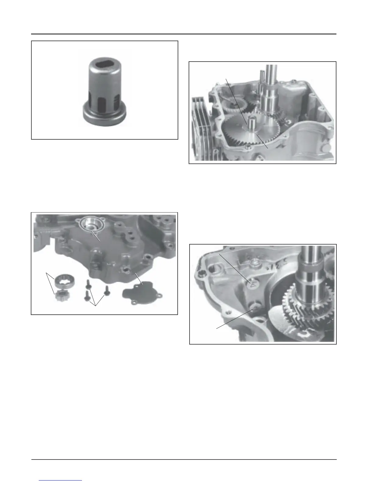
Figure 9-45. Later Style Oil Pressure Relief Valve.
*NOTE: Later style one-piece relief valves (Figure
9-45) are staked in place and do not require
removal unless replacement is intended.
4. Remove the three hex flange screws, oil pump
cover, O-Ring, and oil pump rotors. See Figure
9-46.
Remove Camshaft and Hydraulic Lifters
1. Remove the camshaft and shim. See Figure 9-47.
Figure 9-47. Removing Camshaft.
2. Mark or identify the hydraulic lifters as either
intake or exhaust. See Figure 9-48. Remove the
lifters from the crankcase.
NOTE: The intake hydraulic lifter is farthest from
the crankcase gasket surface. The exhaust
hydraulic lifter is nearest to the crankcase
gasket surface.
Figure 9-46. Removing Oil Pump.
Oil Pump
Cover
Hex Flange Screws
Oil Pump
Rotors
O-Ring
Figure 9-48. Identifying Hydraulic Lifters.
NOTE: Do not use a magnet to remove hydraulic
lifters.
NOTE: Some applications do not require
cylinder head removal for lifter
replacement.
Exhaust Valve
Lifter
Intake Valve
Lifter
Shim
Camshaft
 Loading...


