9.11
Section 9
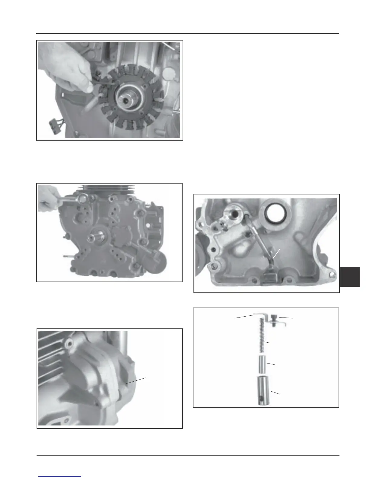
Disassembly
9
Figure 9-40. Removing Stator.
Remove Closure Plate
1. Remove the twelve hex flange screws securing the
closure plate to the crankcase. See Figure 9-41.
Figure 9-41. Removing Closure Plate.
2. Locate the splitting notches in the seam of the
closure plate and crankcase. See Figure 9-42. Pry
the closure plate from the crankcase using a large
flat-blade screwdriver.
NOTE: Insert the screwdriver only in the splitting
notches. Do not pry on the gasket surfaces of
the closure plate or crankcase as this can
cause leaks.
Remove Oil Pickup, Oil Pressure Relief
Valve, Oil Pump, and Oil Seal
1. Remove the oil seal from the closure plate. See
Figure 9-43.
2. Remove the hex flange screw, clip, oil pickup, and
O-Ring seal.
3. Identify the type of oil pressure relief valve used.
If the relief valve assembly is like that shown in
Figure 9-44, remove the hex socket screw,
retaining bracket, valve body, piston, and spring.
If the relief valve is like that shown in Figure 9-45
removal is not necessary. See the note on the next
page.
Figure 9-42. Splitting Notch of Closure Plate/
Crankcase.
Figure 9-43. Removing Oil Seal and Pickup.
Figure 9-44. Removing Oil Pressure Relief Valve
Body, Piston, and Spring (Early Style).
Relief Valve
Bracket
Hex Socket
Screw
Spring
Piston
Valve Body
Splitting
Notch
Oil Pickup
 Loading...


