9.5
Section 9
Disassembly
9
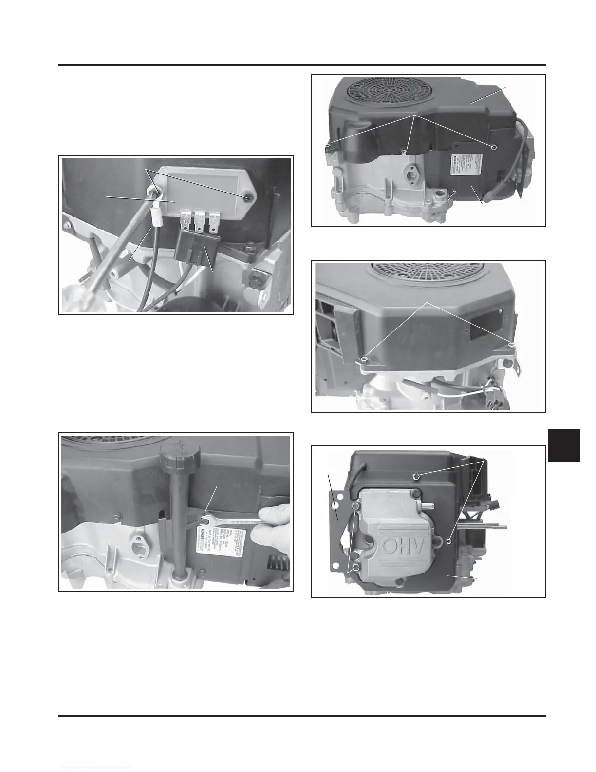
Figure 9-14. Removing Oil Fill Tube.
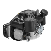
Remove Blower Housing and Baffl es
1. See Figure 9-15, 9-16, and 9-17. Remove the
six screws securing the blower housing and any
commonly mounted clamps/brackets. Remove
the blower housing.
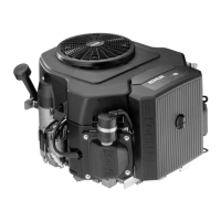
Remove Rectifi er-Regulator (If Required)
1. Remove the connector from the rectifi er-regulator.
See Figure 9-13.
2. Remove the two screws securing the rectifi er-
regulator and individual ground lead (if used).
Figure 9-15. Removing Blower Housing and
Baffl es.
Figure 9-17. Removing Blower Housing and
Baffl es.
2. Remove the hex. fl ange valve cover screws
and any loose spacers (stamped steel valve
covers) which also attach the muffl er and/or lift
bracket. Note the assembly orientation for proper
reassembly later.
Oil Fill Tube
Hex. Flange Screw
Muffl er
Bracket
Valve Cover
Screws
Hex. Flange
Screws
Cylinder Head
Baffl e
Hex. Flange Screws
Connector
Rectifi er-
Regulator
Ground Lead
Mounting Screws
Cylinder
Baffl e
Cylinder Baffl e
Mounting Screw
Blower
Housing
Figure 9-13. Removing Rectifi er-Regulator (not on
all models).
Remove Extended Oil Fill Tube
1. Remove the hex. fl ange screw securing the oil fi ll
tube to the blower housing/crankcase. See Figure
9-14.
2. Pull the oil fi ll tube out of the crankcase fl ange.
Figure 9-16. Removing Blower Housing and
Baffl es.
Mounting Screws