9.6
Section 9
Disassembly
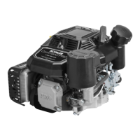
Figure 9-18. Removing Carburetor.
4. Remove the carburetor gasket.
5. If necessary, the carburetor, throttle linkage and
governor lever can be separated. Reattach the
bushings to the linkage following separation to
avoid losing them.
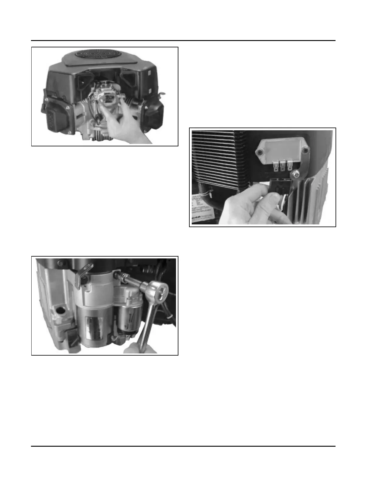
Remove Electric Starter Motor
1. Disconnect the leads from the starter.
2. Remove the two hex. flange screws. See Figure
9-19.
Remove Outer Baffles and Blower
Housing
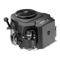
1. Disconnect the wire leads from the start switch on
the blower housing (if so equipped). Disconnect
the plug from the rectifier-regulator. Use the tip of
the dipstick or a similar small flat tool to bend the
locking tang, then remove the B+ terminal from
the center position in the plug. See Figure 9-20.
This will allow the blower housing to be removed
without disturbing the wiring harness.
Figure 9-19. Removing Electric Starter Motor.
3. Remove the starter assembly and lift bracket.
Some inertia drive starters use a separate starter
cover and spacers.
Figure 9-20. Disconnecting Plug from Rectifier-
Regulator.
2. The rectifier-regulator does not have to be
detached from the blower housing. If the engine is
equipped with SMART-SPARK
™
, remove the
mounting screws from the spark advance module
(SAM). See Figure 9-21. The module will hang
loose as part of the wiring harness.
3. Remove the three (each side) hex. flange screws
securing the outer baffles. Note the location of
any lifting strap and the position of the two short
screws (one each side on bottom) for reassembly.
See Figure 9-22.
Kohler Engine Parts Call K&T 606-678-9623 or 606-561-4983
www.mymowerparts.com