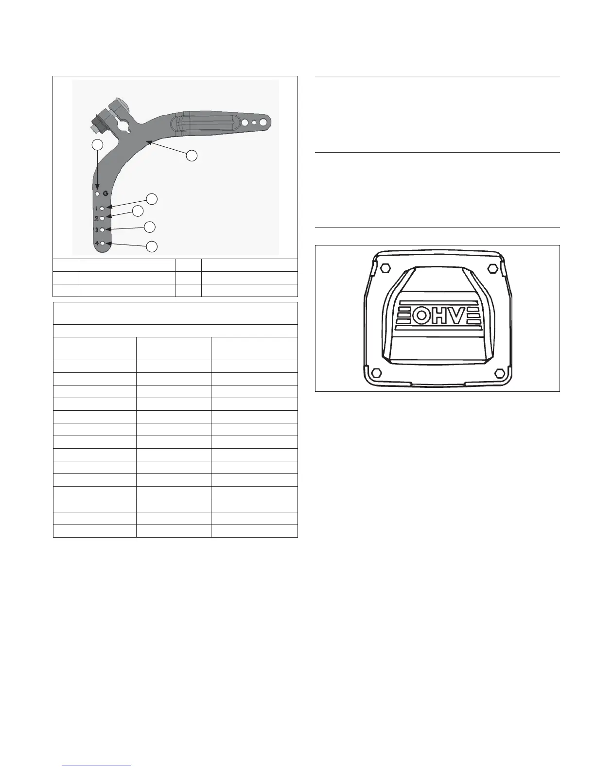
Governor Lever Hole Position
F
A
E
D
C
B
A Governor Lever B Hole 1
C Hole 2 D Hole 3
E Hole 4 F Hole G
Governor Lever and Hole Position/RPM Chart
(Governed Idle, 10% Regulation)
Governed Idle Spring Assembled in Hole G
High Idle RPM
Gov. Lever
Hole No.
Governor Spring
Color Code
3900 3 Black
3850 3 Black
3800 2 Orange
3750 2 Orange
3700 3 Clear
3650 2 Blue
3600 2 Red
3550 2 Clear
3500 2 Clear
3450 2 Clear
3400 1 Black
3350 1 Red
3300 1 Red
3250 3 Yellow
Install Oil Sentry
™
(if equipped)
1. Apply pipe sealant with Tefl on
®
(Loctite
®
PST
®
592™
or equivalent) to threads of Oil Sentry
™
switch and
install it into breather cover. Torque to 4.5 N·m
(40 in. lb.).
2. Connect wire lead (green) to Oil Sentry
™
terminal.
Install Control Panel (if equipped)
1. Install panel to blower housing.
2. Connect throttle control cable or shaft.
3. Connect choke control cable to control bracket.
4. Connect Oil Sentry
™
indicator light wires.
Install Valve Covers
Torque Sequence
1
2
3
4
1. Make sure sealing surfaces are clean.
2. Make sure there are no nicks or burrs on sealing
surfaces.
3. Install a new O-ring in groove of each cover.
4. Locate cover with oil fi ll neck on same side as
removed and install lifting strap in original position.
Position cover on cylinder head. Install four screws
in each cover and fi nger tighten.
5. Torque valve cover fasteners to 6.2 N·m (55 in. lb.)
using sequence shown.
Reassembly
6724 690 34 Rev. D KohlerEngines.com