Electrical System
40
62 690 01 Rev. JKohlerEngines.com
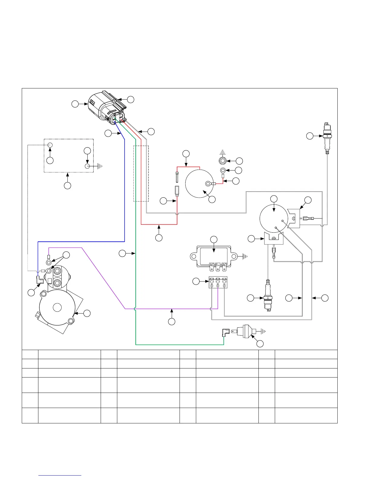
Wire Diagram-15/20/25 Amp Regulated Battery Charging System with CDI/MDI, Four Pin Connector
B
H
G
D
R
B
S
J
P
L
Q
W
E
V
C
T
O
U
A
VM
M
F
B
I
K
N
O
A Blue B Red C Green D Violet (Charging)
E White (Ignition Kill) F Connector G Battery H Battery Positive
I Battery Negative J Starter K Rectier-Regulator L Oil Sentry
™
M Spark Plug(s) N
Flywheel Stator
Assembly
O Ignition Module(s) P Carburetor
Q
Intake Manifold
Screw
R Starter Solenoid Stud S Ground T
Rectier-Regulator
Connector
U
Starter Solenoid
Tang
V
White
(AC Charging Leads)
W Polarity Ribs X Solenoid Lead
A typical xed ignition system consists of:
● 1 magnet assembly which is permanently afxed to ywheel.
● 2 electronic capacitive-discharge (CDI) or magnetic discharge (MDI) ignition modules which mount on engine
crankcase.
● 1 kill switch (or key switch) which grounds modules to stop engine.
● 2 spark plugs.
X