Disassembly/Inspection and Service
60 62 690 01 Rev. JKohlerEngines.com
Use largest stem diameter to calculate clearance by
subtracting stem diameter from guide diameter. If intake
clearance exceeds 0.038/0.076 mm (0.0015/0.0030
in.) or exhaust clearance exceeds 0.050/0.088 mm
(0.0020/0.0035 in.), determine if valve stem or guide is
responsible for excessive clearance.
Maximum (I.D.) wear on intake valve guide is 7.135
mm (0.2809 in.) and 7.159 mm (0.2819 in.) for exhaust
guide. Guides are not removable but can be reamed
0.25 mm (0.010 in.) oversize. Valves with 0.25 mm
oversize stems must then be used.
If guides are within limits but valve stems are worn
beyond limits, install new valves.
Valve Seat Inserts
Hardened steel alloy intake and exhaust valve seat
inserts are press tted into cylinder head. Inserts are
not replaceable but can be reconditioned if not too badly
pitted or distorted. If cracked or badly warped, cylinder
head should be replaced.
Recondition valve seat inserts following instructions
provided with valve seat cutter being used. Final cut
should be made with an 89° cutter as specied for
valve seat angle. Cutting proper 45° valve face angle
as specied, and proper valve seat angle (44.5°, half of
full 89° angle), will achieve desired 0.5° (1.0° full cut)
interference angle where maximum pressure occurs on
outside diameters of valve face and seat.
Inspection and Service
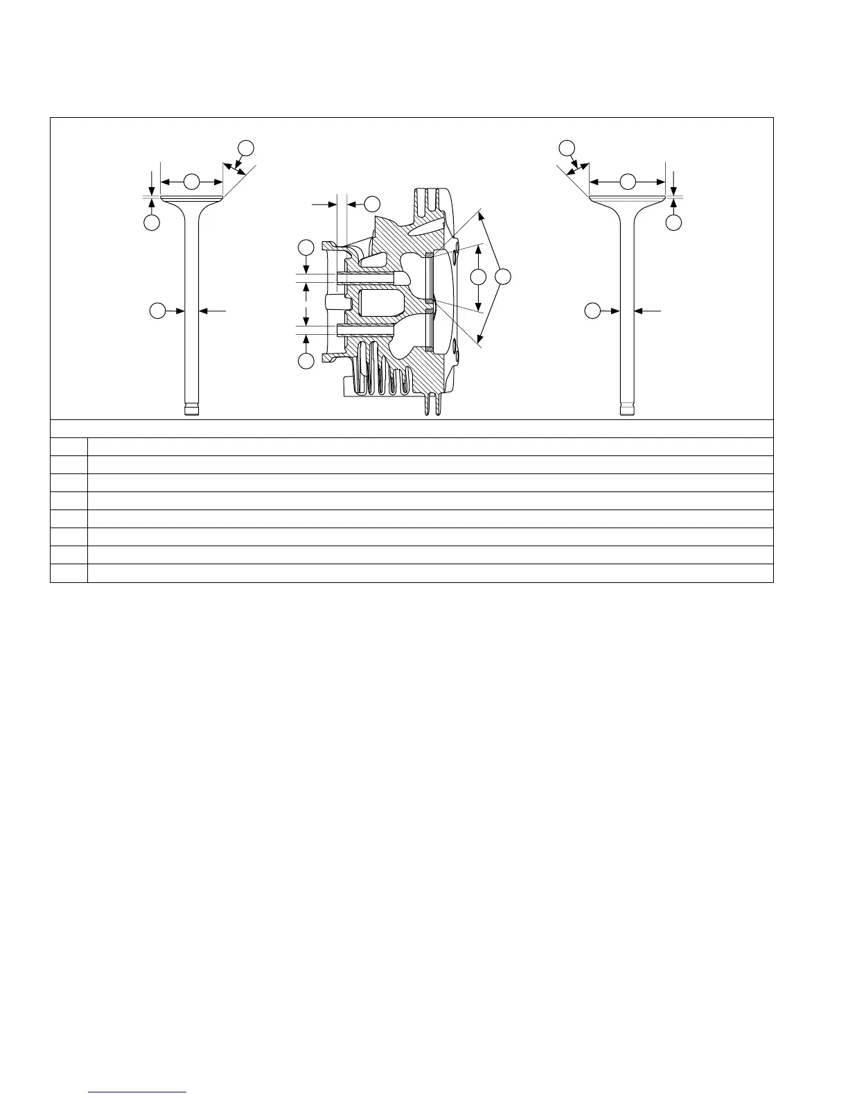
Valve Details
EXHAUST VALVE INTAKE VALVE
EXH
INT
H H
G G
E E
F F
A
C
D
D
B
Dimension Intake Exhaust
A Seat Angle 89° 89°
B Seat Taper 30° 30°
C Guide Depth 8.5 mm (0.334 in.) 8.5 mm (0.334 in.)
D Guide I.D. 7.038/7.058 mm (0.2771/0.2779 in.) 7.038/7.058 mm (0.2771/0.2779 in.)
E Valve Head Diameter 38.625/38.685 mm (1.5206/1.5230 in.) 31.625/31.825 mm (1.2450/1.2549 in.)
F Valve Face Angle 45° 45°
G Valve Margin (Min.) 1.0 mm (0.0393 in.) 1.0 mm (0.0393 in.)
H Valve Stem Diameter 6.982/7.000 mm (0.2749/0.2756 in.) 6.970/6.988 mm (0.2744/0.2751 in.)
After cleaning, check atness of cylinder head and
corresponding top surface of crankcase using a surface
plate or piece of glass and feeler gauge. Maximum
allowable out of atness is 0.076 mm (0.003 in.).
Carefully inspect valve mechanism parts. Inspect valve
springs and related hardware for excessive wear or
distortion. Check valves and valve seat area or inserts
for evidence of deep pitting, cracks, or distortion. Check
clearance of valve stems in guides.
Hard starting or loss of power accompanied by high
fuel consumption may be symptoms of faulty valves.
Although these symptoms could also be attributed to
worn rings, remove and check valves rst. After removal,
clean valve heads, faces, and stems with a power wire
brush.
Then, carefully inspect each valve for defects such as a
warped head, excessive corrosion, or a worn stem end.
Replace valves found to be in bad condition.
Valve Guides
If a valve guide is worn beyond specications, it will not
guide valve in a straight line. This may result in burnt
valve faces or seats, loss of compression, and excessive
oil consumption.
To check valve guide-to-valve stem clearance,
thoroughly clean valve guide and, using a split-ball
gauge, measure inside diameter of guide. Then, using
an outside micrometer, measure diameter of valve stem
at several points on stem where it moves in valve guide.