Electrical System
42
62 690 01 Rev. JKohlerEngines.com
AC
AF
AI
AE
AD
AA
D
B
O
Q
S
Z
X
C
A
D
G
Y
E
B
AH
W
W
W
V
B
U
T
G
G
B
F
F
P
F
B
D
AH
J
J
X
R
G
G
A
B
B
F
B
I
H
N
L
K
J
M
AB
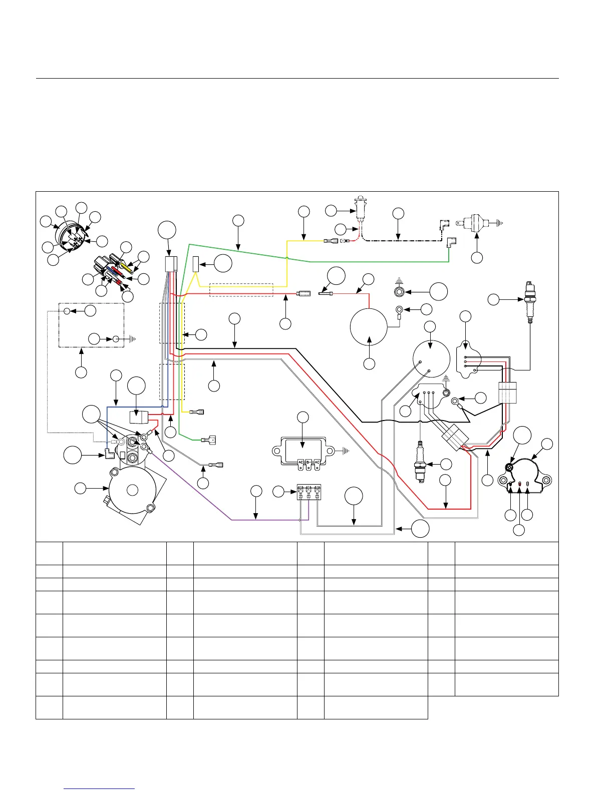
A Blue B Red C
Green (Oil Sentry
™
Pulse Signal)
8
D Yellow (Accessory)
E Violet F White G Black H To Battery
I To Accessory J Ground K To Rectier-Regulator L To Magneto
M To Starter N Key Switch O
Rectier-Regulator
Connector
P Battery
Q Battery Negative R Battery Positive S
Oil Sentry
™
Light
(Optional)
T Oil Sentry
™
U Carburetor V
Flywheel Stator
Assembly
W Ignition Module(s) X Spark Plug(s)
Y Rectier-Regulator Z Starter AA Fuse AB Starter Solenoid Stud
AC
Carburetor Mounting
Stud
AD Starter Solenoid Tang AE Connector (5-Circuit) AF Connector (1-Circuit)
AG Solenoid Lead AH
White
(AC Charging Leads)
AI Spark Plug Lead
Digital Spark Advance Ignition (DSAI) System
This system uses a digital microprocessor which is located in ignition modules. Ignition timing varies depending upon
engine speed with this system. There are 2 inductive-style ignition modules that control ignition timing based on
engine RPM. A typical DSAI application consists of:
● 1 magnet assembly, which is permanently afxed to ywheel.
● 2 inductive, 12-volt ignition modules, which mount on engine crankcase.
● 1 12-volt battery, which supplies current to ignition modules.
● 1 kill switch (or key switch) which grounds spark advance module to stop engine.
● 2 spark plugs.
Wire Diagram-15/20/25 Amp Regulated Battery Charging System with DSAI Ignition, Five Pin Connector and
Key Switch
8
Not valid with indicator light or no pressure switch.
AG
B