Electrical System
36 32 690 01 Rev. GKohlerEngines.com
Digital Spark Advance Ignition (DSAI) Ignition System
This system uses a digital microprocessor which is located in ignition modules. Ignition timing varies depending upon
engine speed with this system. There are 2 inductive-style ignition modules that control ignition timing based on
engine RPM. A typical DSAI application consists of:
● 1 magnet assembly, which is permanently affi xed to fl ywheel.
● 2 inductive, 12-volt ignition modules, which mount on engine crankcase.
● 1 12-volt battery, which supplies current to ignition modules.
● 1 kill switch (or key switch) which grounds spark advance module to stop engine.
● 2 spark plugs.
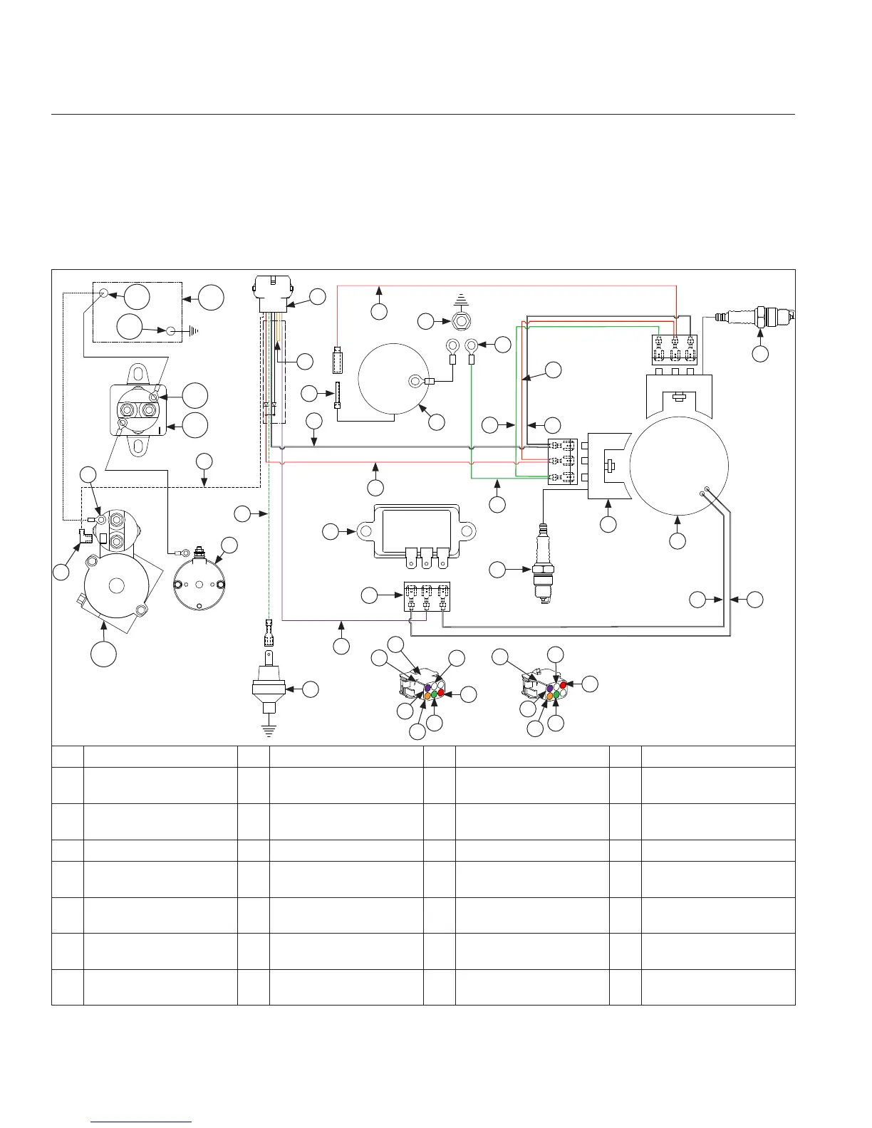
Wiring Diagram-Digital Spark Advance Ignition (DSAI) System
R
N
O
U
A
B
C
E
D
F
F
I
H
G G
B
B
J
J
L
K
M
N
J
W
X
Y
Z
Q
P
B
T
V
V
U
P
B
J
N
N
S
AB
AD
AF
AE
AC
AA
A Oil Sentry
TM
(Optional) B Green C Violet (Charging) D Rectifi er-Regulator
E
Rectifi er-Regulator
Connector
F Spark Plug(s) G
White
(AC Charging Leads)
H Ignition Module(s)
I
Flywheel Stator
Assembly
J Red K Ground L Intake Manifold Screw
M Carburetor N White O Solenoid Lead P Orange
Q Connector R Red (shown) or Blue S
Solenoid Shift Starter
Assembly (Optional)
T Orange (shown) or Red
U
Violet (shown) or
Orange
V Polarity Rib W
To Starter Solenoid
Tang
X
Inertia Drive Starter
Assembly
Y Starter Solenoid Stud Z Starter Solenoid Tang AA
Solenoid Shift Starter
Assembly (Optional)
AB Battery Positive
AC Battery Negative AD Battery AE Relay Stud AF
Relay Cranking
(Customer Supplied)
 Loading...