Home
Kohler
Engine
Courage SV470-600
Kohler Courage SV470-600 User Manual
4
of 1
of 1 rating
112 pages
Give review
Manual
Specs
To Next Page
To Next Page
Loading...
1
C
OURAGE
™
S
ERIES
SV470-600
S
ER
VICE
M
ANUAL
V
ERTICAL
C
RANKSHAFT
Not For Resale
www.SmallEngineDiscount.com
2
Table of Contents
Table of Contents
2
Safety Precautions
3
Section 1. Safety and General Information
3
Explanation of Engine Identification Numbers
5
Oil Recommendations
6
Oil Type
6
Fuel Recommendations
6
Gasoline/Alcohol Blends
6
Storage
7
Maintenance Schedule
7
Periodic Maintenance
7
Safety and General Information
8
General Specifications
9
General Torque Values
15
Metric Fastener Torque Recommendations for Standard Applications
15
Oil Drain Plugs Tightening Torque: N-M (English Equiv.)
15
Torque Conversions
15
Flywheel Holding Tool
16
Section 2. Special Tools
16
Rocker Arm/Crankshaft Tool
17
Section 2 Special Tools
17
Section 3. Troubleshooting
18
External Engine Inspection
19
Cleaning the Engine
19
Basic Engine Tests
20
Crankcase Vacuum Test
20
Incorrect Vacuum in Crankcase
20
Leakdown Test Results
21
Cylinder Leakdown Test
21
Leakdown Test Instructions
21
Compression Test
21
Air Cleaner Assembly-Exploded View
22
Precleaner Service
22
Section 4. Air Cleaner and Air Intake System
22
Paper Element Service
23
Inspect Air Cleaner Components
23
Bushings in Air Cleaner Base
23
Disassembly
24
Breather Hose
24
Clean Air Intake/Cooling Areas
25
Fuel Type
26
Gasoline/Ether Blends
26
Section 5. Fuel System and Governor
26
Fuel Pump
27
Repair
27
Fuel Filter
27
Fuel System Troubleshooting Guide
27
Pulse Fuel Pump
28
Carburetor
28
Troubleshooting–Fuel System
28
Carburetor Adjustment
29
Fixed Main Jet Carburetor
29
Low Idle Mixture Adjustment
30
Optimum Low Idle Fuel Setting
30
Low Idle Speed Setting
30
Welch Plug Removal
31
Carburetor-Exploded View
31
Choke Shaft Removal
32
Throttle Shaft Removal
32
Cleaning
32
Main Fuel Jet Removal
32
Inspection
33
Choke Shaft Installation
33
Welch Plug Installation
33
Carburetor Reassembly
33
Throttle Cable Adjustment
34
Fuel Shut-Off Solenoid
34
Unitized Throttle and Choke Control
34
High Altitude Operation
34
Adjusting Unitized Throttle/Choke Control
35
Typical Throttle/Choke Controls
35
Starting an Engine Equipped with Unitized Throttle and Choke Control
35
Throttle Position for Starting Engine
35
Choke Adjustment
36
High Speed (RPM) Adjustment
36
Adjusting High Speed (RPM)
36
Choke Control Installation
37
Separate Throttle and Choke Control
37
Throttle Control Installation
37
Install Separate Control Cables
37
Changing the High Speed (RPM) on the Engines with Separate Controls (Increase or Decrease RPM)
38
Governed Idle Adjustment
38
Location of Governed Idle Adjusting Screw
38
Governor Gear/Flyweight Assembly
38
Operation
39
Initial Adjustment
39
Tightening Governor Lever Nut
39
Governor Sensitivity Adjustment
40
Governor Spring Location Chart
40
Viscosity Grades Table
41
Check Oil Level
41
Section 6. Lubrication System
41
Oil Drain Plug, Oil Filter
42
Oil Level Dipstick
42
Removing Dipstick
42
Change Oil and Oil Filter
42
Full-Pressure Lubrication System
43
Service
43
Oil Filter
43
Oil Sentry
43
Testing Oil Pressure
44
Testing the Oil Sentry Switch
44
Oil Sentry Pressure Switch Location
44
Installation
44
Spark Plug Service
45
Section 7. Electrical System and Components
45
Electronic CD Ignition System
47
Capacitive Discharge Ignition Module
48
Troubleshooting and Testing CD Ignition Systems
48
Preliminary Test
48
Testing CD Ignition Module Secondary
49
CD Ignition System Troubleshooting Guide
49
Ignition Tester, SPX Part No. KO1046
49
Battery Maintenance
50
Battery Test
50
Electrical Systems Wiring Diagrams and Battery Charging Systems
50
Battery Charging
50
3 Amp Unregulated Battery Charging System/70 Watt Lighting
51
Troubleshooting Guide 3 Amp Battery Charging System with 70 Watt Lighting Stator
52
Troubleshooting Guide 3 Amp/70 Watt Braking Stator
53
9 Or 15 Amp Regulated Battery Charging System
55
9 Or 15 Amp Stator and Rectifier-Regulator
56
Proper Connection to Test 9 or 15 Amp Charging System
56
Troubleshooting Guide 9 or 15 Amp Regulated Battery Charging System
57
Electric Starters
58
Troubleshooting Guide-Starting Difficulties
58
Drive Components
59
Assembling Inner Half of Tool Around the Armature Shaft and Retaining Ring
59
Starter Removal and Installation
59
Starter Drive Service
59
Retaining Ring Installation
60
Assembling Larger Inner Half Around Spring Retainer
60
Starter Disassembly
60
Inertia Drive Electric Starter
60
Commutator Service
61
Starter Reassembly
61
Removing Brush Carrier Assembly
61
Brush Replacement
61
Installing Brush Carrier Using Staples
62
Torquing Thru Bolts
62
Assembled Starter
62
Typical Disassembly Sequence
63
Drain Oil from Crankcase and Remove Oil Filter
63
Oil Drain Location, Oil Filter, and Oil Fill Cap/Dipstick
63
Section 8. Disassembly
63
Remove Electric Starter
64
Remove Muffler
64
Remove Blower Housing
64
Remove Oil Sentry Pressure Switch (on Models so Equipped)
64
Removing Electric Starter
65
Air Cleaner Components
65
Remove External Governor Components, Carburetor, and Fuel Pump
65
Remove Air Cleaner
65
Disconnecting Fuel Line from Carburetor
66
Disconnecting Pulse Line from Fitting
66
Removing Heat Deflector Screw and Ground Lead
66
Disconnecting Fuel Solenoid Lead
66
Removing Heat Deflector
67
Removing Speed Control Bracket from Closure Plate
67
Removing Governor Lever
67
Disconnecting Governor Spring
67
Remove Ignition Module
68
Removing Lead from Clip (RFI Suppression Equipped Units)
68
Remove Grass Screen, Fan, and Flywheel
68
Removing Fan and Flywheel Mounting Hardware
68
Valve Cover and Gasket Details
69
Remove Valve Cover and Cylinder Head
69
Removing Flywheel Using Puller
69
Remove the Stator
69
Removing Cylinder Head Bolts and Washer
70
Removing Cylinder Head and Gasket
70
Disassemble Cylinder Head
70
Removing Spark Plug
70
Remove Closure Plate
71
Closure Plate and Gasket Removed from Crankcase
71
Removing Valves with Spring Compressor
71
Disassembling Rocker Arm Components
71
Disassemble Closure Plate
72
Removing Governor Gear
72
Remove Cam Gears, Cam Shafts, and Oil Pump
72
Removing Exhaust Side Cam Shaft and Slotted Thrust Washer
73
Intake Cam Shaft and Oil Pump Assembly
73
Remove Connecting Rod and Piston
73
Removing Connecting Rod Cap
73
Balance Weight Disassembly
74
Remove Piston from Connecting Rod
74
Remove Crankshaft and Balance Weight Assembly
74
Remove Piston Rings
74
Removing Crank Gear Key
75
Removing Balance Weight Screw
75
Disassembled Balance Weight
75
Remove Governor Cross Shaft
75
Remove PTO and Flywheel Side Oil Seals
76
Automatic Compression Release (ACR)
77
ACR Details
77
Section 9. Inspection and Reconditioning
77
Cam Gears
78
Crankshaft and Crank Gear
78
Crankcase
78
Honing
78
Measuring Piston-To-Bore Clearance
79
Measuring Piston Diameter
79
Balance Weight Assembly
79
Measuring Balance Weight Guide Pin and Guide Shoe-To-Closure Plate Guide Channel Running Clearance
80
Balance Weight-To-Eccentric Clearance
80
Measuring Balance Weight to Crankshaft Eccentric Ring(S) Clearance
80
Measuring Guide Pin O.D.
81
Measuring Guide Shoe Hole I.D.
81
Flywheel
81
Cylinder Head and Valves
82
Valve Details
82
Valve Guides
85
Valve Seat Inserts
85
Lapping Valves
85
Pistons and Rings
85
Common Types of Piston and Ring Damage
86
Some Important Points to Remember When Servicing Piston Rings
87
Measuring Piston Ring End Gap
87
Measuring Piston Ring Side Clearance
87
Install Piston Rings
87
Procedure to Install Governor Shaft
88
Oil Pump Assembly and Pressure Relief Valve
88
Governor Gear and Shaft
88
Connecting Rods
88
Install PTO Side Oil Seal
90
Section 10. Reassembly
90
Install Governor Cross Shaft
91
Install Oil Pump Assembly and Intake Cam Shaft
91
Installing Oil Pump and Lower Drive Pin on Intake Cam Shaft
91
PTO Seal Depth Details
91
Assembled Intake Cam Shaft Details
92
Gerotor Gears Installed in Oil Pump
92
Installing Oil Pump Outlet Seal
92
Oil Pump Outlet Seals
92
Checking Outlet Seal Passage Opening (Open Style)
93
Install Crankshaft and Balance Weight
93
Installing Crank Gear Key
93
Torquing Oil Pump Mounting Screws
93
Assembled Piston and Connecting Rod
94
Install Piston and Connecting Rod
94
Install Piston to Connecting Rod
94
Installing Crankshaft Assembly
94
Direction Arrow on Piston
95
Install the Exhaust Cam Shaft and Cam Gear
95
Installing Cam Levers
95
Installing Piston and Connecting Rod
95
Exhaust Cam Shaft Installation
96
Hooking ACR Spring Onto Exhaust Cam Gear
96
Installing Exhaust Cam Gear
96
Spring Installed on ACR Weight
96
Install Closure Plate Gasket, Closure Plate, and Wiring Harness
97
Install Crank Gear
97
Install Flywheel Side Oil Seal
97
Install Intake Cam on Cam Shaft
97
Aligning and Installing Closure Plate
98
Assemble Cylinder Head
98
Closure Plate Installed
98
Install Cylinder Head
98
Install Rocker Arms and Push Rods
99
Installing Cylinder Head Fasteners
99
Installing Drain Back Check Ball
99
Installing Head Gasket
99
Adjusting Valve Clearance (Lash)
100
Install Valve Cover
100
Installing Push Rods and Rocker Arm Assemblies
100
Locking Adjustment Nut Set Screw
100
Connecting Pulse Line to Fitting
101
Install Pipe Plug or Fitting and Pulse Line for Fuel Pump
101
Install Stator and Wiring Harness
101
Installing B+Lead into Connector
101
Install Fan and Flywheel
102
Installing Fan and Mounting Hardware to Flywheel
102
Torquing Flywheel
102
Install Electric Starter
103
Install Ignition Module
103
Setting Air Gap
103
Tightening Clip Around Sheathing
103
Install Heat Deflector, Carburetor, Linkage and Air Cleaner Base
104
Install New Spark Plug
104
Installing Intake Gasket and Heat Deflector
104
Mounting Stud Installed
104
Connecting Fuel Line to Carburetor
105
Fuel Solenoid Lead Secured with Tie Strap
105
Installing Carburetor Assembly with Linkages
105
Securing Ground Lead
105
Install and Adjust Governor Lever
106
Installing Air Cleaner Base
106
Installing Mounting Screw
106
Torquing Air Cleaner Fasteners
106
Attaching Speed Control Bracket
107
Connecting Choke Linkage and Governor Spring
107
Install Fuel Pump (if Equipped)
107
Mounting Speed Control Bracket
107
Install Blower Housing and Flywheel Screen
108
Install Rectifier-Regulator
108
Installing Blower Housing Screws
108
Installing Fuel Pump
108
Install Air Cleaner Element, Precleaner, and Air Cleaner Cover
109
Install Oil Sentry or Pipe Plug
109
Installing Grass Screen
109
Installing Pipe Plug or Adapter
109
Install Muffler
110
Installing Air Cleaner Cover
110
Installing Precleaner
110
Install Drain Plug, Oil Filter, and Oil
110
Prepare the Engine for Operation
111
Testing the Engine
111
4
Based on 1 rating
Ask a question
Give review
Questions and Answers:
Need help?
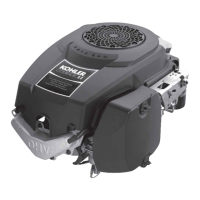
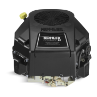
Do you have a question about the Kohler Courage SV470-600 and is the answer not in the manual?
Ask a question
Kohler Courage SV470-600 Specifications
General
Compression Ratio
8.5:1
Fuel Type
Gasoline
Cooling System
Air-cooled
Starter Type
Electric
Oil Capacity
1.5 qt (1.4 L)
Cylinder Configuration
Single
Related product manuals
Kohler COURAGE SV470-610
16 pages
Kohler Courage SV470
132 pages
Kohler Courage SV480
48 pages
Kohler Courage SV590
76 pages
Kohler Courage SV740
8 pages
Kohler Courage SV725
8 pages
Kohler Courage SV600
48 pages
Kohler COURAGE SV710-740
20 pages
Kohler Courage PRO SV840
8 pages
Kohler Courage PRO SV820
8 pages
Kohler Courage PRO SV830
8 pages
Kohler Courage SH265
18 pages