110
Section 7 Decision-Makerr 6000 Controller TP-6356 4/12
5. Disconnect the existing controller electrical
connections.
a. Remove the controller cover. If access to the
interconnection circuit board on the rear panel
and/or the main logic/communication circuit
board on the front panel is difficult to access,
partially disassemble the controller box.
Remove the two controller panel top screws
and center bottom screw and then loosen the
bottom screw on each side to swing the
controller panel down. See Figure 7-5.
Note: If the controller is panel mounted to the
junction box, remove the access panel
and respective hardware.
Note: Clearly mark all disconnected leads
from the controller with tape to simplify
reconnection.
b. Disconnect the controller harness leads. Listed
below are some common leads and plugs that
require removal or disconnection. Items below
in bold are shown in Figure 7-5 and Figure 7-6.
These connections are typical and may not
apply to all applications. See the
corresponding wiring diagram found in the
wiring diagrams manual.
D AC fuse terminal block TB5 leads V7, V8,
and V9
D AC fuse terminal block TB12 leads F1, F2,
and F3
D Voltage sensing lead V0
D All external connections to terminal strips
TB1, TB2, TB3, and TB4
D Plug P24 to CT burden resistor board
D Plug P23 to the controller connection strip in
the junction box
D Plug P1 to the engine wiring harness
D Plug P18 remote communication connection
(RS-232)
D Plug P21 PGEN communication connector
to other controllers
D Plug P22 CAN communication connector to
the engine control module
D Prime power kit
D Any other external leads to the controller
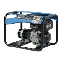
GM65729-A
56
1. AC fuse block (TB5)
2. AC fuse block (TB12)
3. Interconnection circuit board
4. Interface circuit board
5. P18 on main logic (microprocessor)/communication circuit
board
6. Keypad and digital display circuit boards
7. Customer connection terminal strip
8. Indicator circuit board (lamps and alarm horn)
9. P24 to CT burden resistor board
8
34
7
1
2
Figure 7-5 Disconnecting Controller Circuit Board
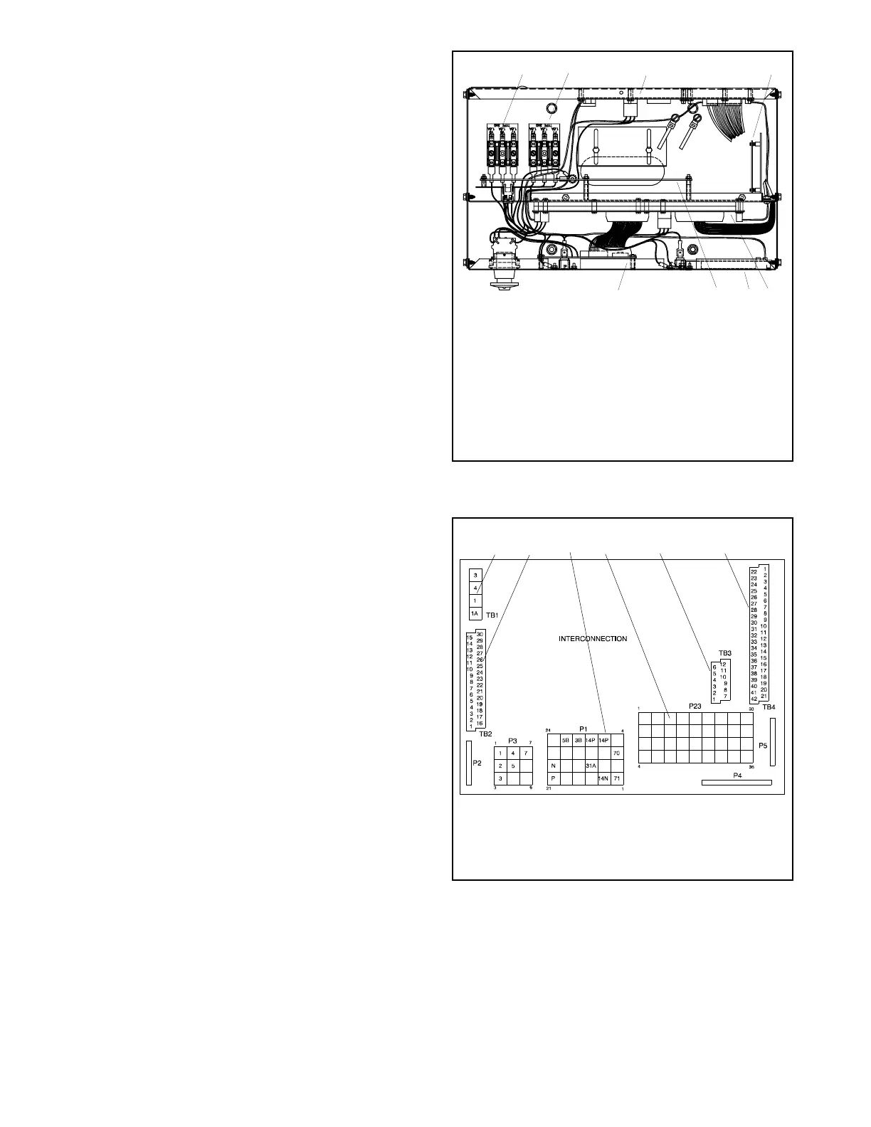
External Wiring Connections
1. TB1 terminal strip
2. TB2 terminal strip
3. P1 Connector
ADV-6533-A
2
4
1
56
4. P23 Connector
5. TB3 terminal strip
6. TB4 terminal strip
3
Figure 7-6 Interconnection Circuit Board Terminal
Strips and Connectors
 Loading...