111
Section 7 Decision-Makerr 6000 ControllerTP-6356 4/12
6. Remove the existing controller.
Note: If the controller is panel mounted to the
junction box, remove the access panel and
respective hardware to remove the
controller components.
a. Remove the junction box panel(s) to gain
access to the controller vibromount screws.
b. Remove the four controller vibromount screws
from underneath the junction box top panel.
c. Remove the braided ground strap.
d. Lift off the existing controller.
7. Install the replacement controller.
Note: If the controller is panel mounted to the
junction box, install the access panel and
respective hardware to mount the controller
components.
a. Place the replacement controller on the
junction box top panel holes.
b. Align the controller vibromounts with the
mounting holes and install four screws.
c. Connect the braided ground strap.
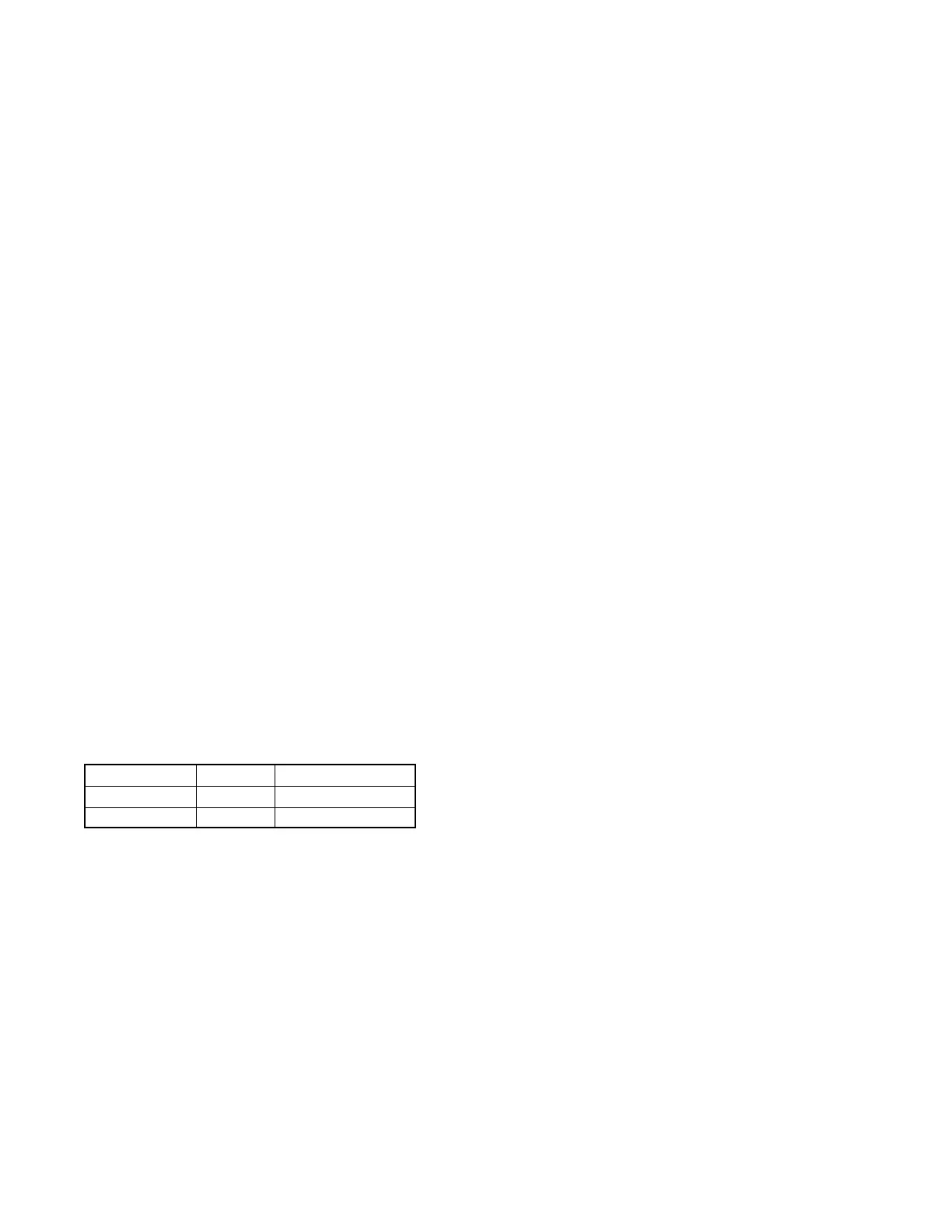
d. Order and Install the controller’s front display
lamps, if required. See Figure 7-4 for location.
See Figure 7-7 for lamp identification. The
controller uses either 12-volt or 24-volt lamps
matching the engine electrical system.
Determine the engine electrical system voltage
using the generator set nameplate information.
Lamp Part No. Voltage Bulb Part Number
255126 12 1892
283420 24 313
Figure 7-7 Lamp Identification
8. Connect the replacement controller.
a. Remove the controller cover. If access to the
interconnection circuit board on the rear panel
and/or the communication circuit board on the
front panel is difficult, partially disassemble the
controller box. Remove the two controller
panel top screws and center bottom screw and
then loosen the bottom screw on each side to
swing controller panel down. See Figure 7-5.
b. Reconnect the controller wiring that was
previously removed. See Figure 7-5,
Figure 7-6, and the corresponding wiring
diagram found in the wiring diagrams manual.
Listed below are some common leads and
plugs that may require reconnection. These
connections are typical and may not apply to all
situations.
D AC fuse terminal block TB5 leads V7, V8,
and V9
D AC fuse terminal block TB12 leads F1, F2,
and F3
D All external connections to terminal strips
TB1, TB2, TB3, and TB4
D CT/meter scale terminal block lead V0
D P24 connector to CT burden resistor board
D Plug P23 to the controller connection strip in
the junction box
D Plug P1 to the engine wiring harness
D Plug P18 remote communication connection
(RS-232)
D Plug P21 PGEN communication connector
to other controllers
D Plug P22 CAN communication connector to
the engine control module
D Prime power kit
D Any other external leads to the controller
c. Swing the rear controller panel up and replace
and tighten the screws, as necessary.
d. Replace the junction box panel(s) and screws.
9. Restore power to the generator set.
a. Reconnect the generator set engine starting
battery, negative (--) lead last.
b. Reconnect power to the battery charger, if
equipped.
 Loading...