112
Section 7 Decision-Makerr 6000 Controller TP-6356 4/12
10. Install the program/data files.
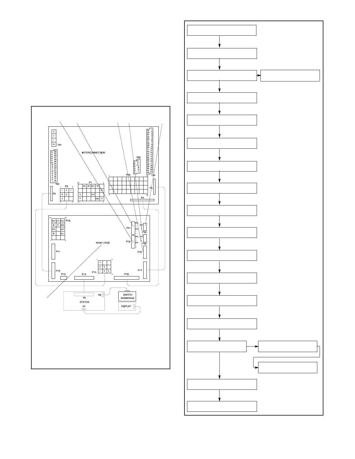
a. Connect the PC to the controller at P19
(RS-485). See Figure 7-8.
b. Insert the personality profile backup disk/drive
and load the data. Refer to Tech Tools—
Software and TP-6701 SiteTecht Software
Operation Manual for details.
c. Use the controller keypad to go to Menu 20,
Factory Setup. See Figure 7-9 for displays.
1. P19—RS-485 port (Modbusr to DPS, SiteTecht software,
Ethernet converter)
2. P21—PGEN paralleling connection, RS-485 port
3. P18—Modbusr, RS-232 port (Monitor III connection)
4. P20—Modbus, RS-485 port (Modbusr to remote serial
annunciator [RSA] or Ethernet converter)
5. P22—ECM (CAN) connector
6. Main logic circuit board
ADV-6533-A
12 34 5
6
Figure 7-8 Main Logic Circuit Board Communication
Ports (Top View of Circuit Board)
MENU 20
FACTORY SETUP
FINAL ASSEMBLY DATE
DD/MM/YY
FINAL ASSEMBLY →
CLOCK NO ?
OPERATING DAYS →
#
MODEL NO #
SPEC NO #
GENSET SERIAL NO #
ALTERNATOR PART NO #
ENGINE PART NO #
SERIAL NO #
CONTROLLER SERIAL NO
SETUP LOCK YES
ENTER CODE ?
(UNLOCKS SETUP)
INITIALIZE BLOCK? Y/N
(data block failure code)
INITIALIZE EEPROM? Y/N
CODE VERSION #.#
COPYRIGHT ####
TEMP SENSOR →
GM##### Y/N
DISABLE LOW COOLANT
TEMP WARNING Y/N
TEST OVERSPEED
SHUTDOWN Y/N
(right arrow scroll thru available
sensors) (non-ECM models only)
(DD/MTU models with MDEC
only)
(DD/MTU models with MDEC
only)
REGULATOR →
PARAMETERS
Figure 7-9 Menu 20, Factory Setup
 Loading...