22 Section 1 Specifications TP-6953 7/19
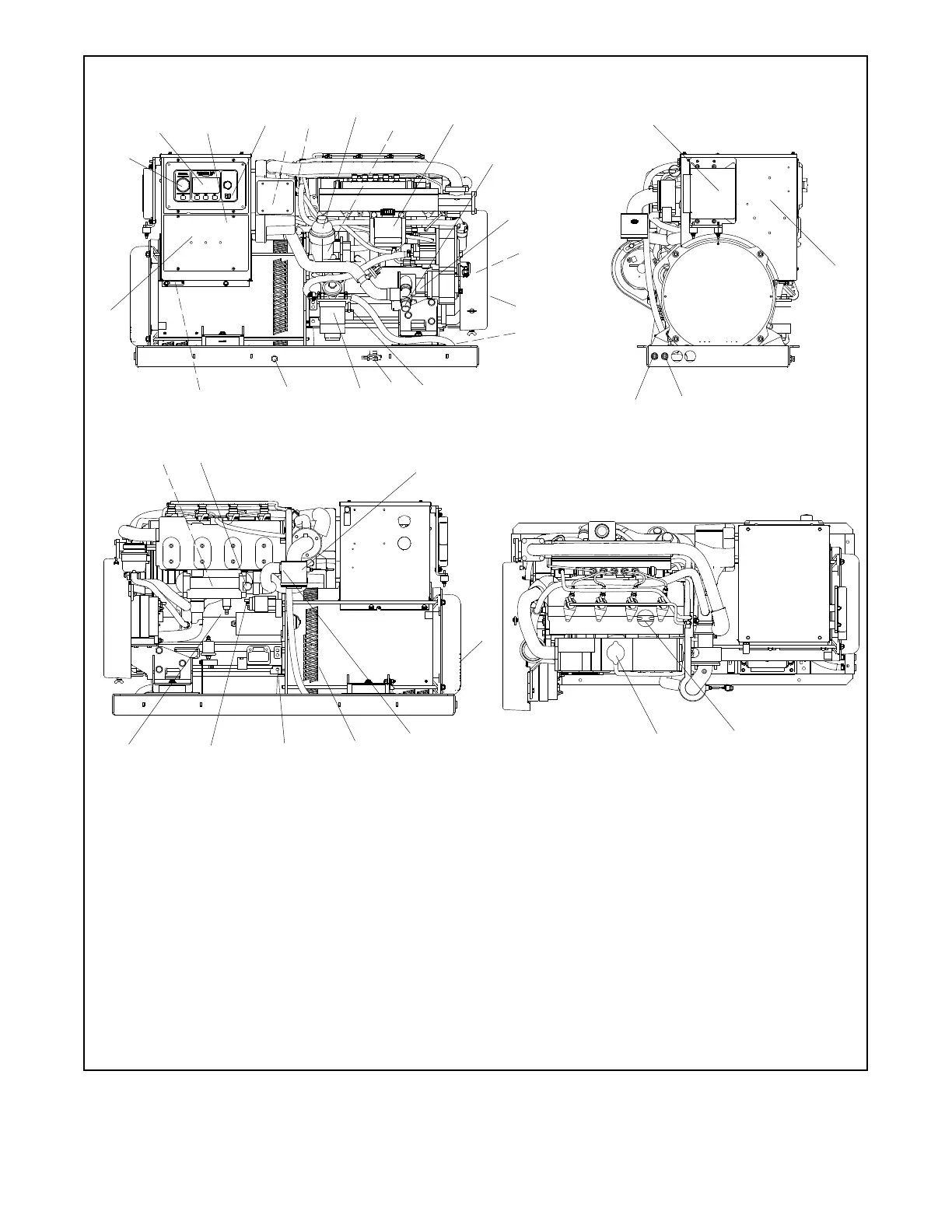
1. Emergency stop
2. Decision-Makerr 3500 controller
3. Nameplate (on front of junction box)
4. USB port
5. Air filter element
6. Lifting eye
7. Oil filter cartridge cover
8. Oil filter c artridge
9. Coolant overflow bottle
10. Seawater inlet
11. Seawater pump
12. V -belt (battery charging alternator)
13. Belt guard
14. Fuel pump
15. Oil check/dipstick
16. Oil drain valve (on engine)
17. Fuel filter
18. Oil drain
19. Customer load lead connection
20. Optional circuit breaker location
21. Fuel return connection
22. F uel supply connection
23. ECU
24. Location for 24- to 12-volt converter, if equipped
25. Heat exchanger internal to exhaust manifold
26. Anticorrosion zinc anode
27. Water cooled exhaust outlet
28. Alternator cooling air inlet
29. Engine coolant drain
30. Battery positive (+) c onnection
31. Battery negative (- ) connection
32. Alternator air outlet
33. Seawater drain (remove hose clamp)
34. Coolant fill/coolant overflow tube
35. Oil fill
1
4
16
30
17
27
19
14
10
31
9
6
3
25
32
2
20
33
Non Service-Side View
ADV8857-
21
28
35
29
34
11
Top View
End View
Service -Side View
26
12
13
15
7
8
18
22
5
23
24
Figure 1 -3 Service Views—Typical (32- 40EKOZD and 28- 35EFKOZD Models)
 Loading...