23Section 1 SpecificationsTP-6953 7/19
1.4 Introduction
The specification sheets for each generator set provide
specific alternator and engine information. Refer to the
respective specification sheet for data not supplied in
this manual. Consult the generator set operation
manual, installation manual, engine operation manual,
and engine service manual for additional specifications.
Voltage regulation is provided by the generator set
controller. Refer to the Operation Manual for additional
voltage regulator information.
1.5 Wound-Field Alternator
Concept—13- 32EKOZD and
11- 28EFKOZD Models
The alternator is identified with one of the following
designations: 4D_ or 4E_. Example: Gen. Model
4D3.1. The first alpha character (D) identifies the
alternator family.
These generator sets utilize a wound-field alternator to
produce AC voltage. Upon activation of the generator
master switch, DC current from the battery magnetizes
the r otor (field). When the magnetized rotor rotates
within the stator windings, an electrical voltage develops
within the stator. As engine speed and generator output
increase, the voltage regulator feeds rectified stator
output current to the rotor through the exciter to increase
the strength of the rotor field. As the rotor field increases
in strength, generator output also increases.
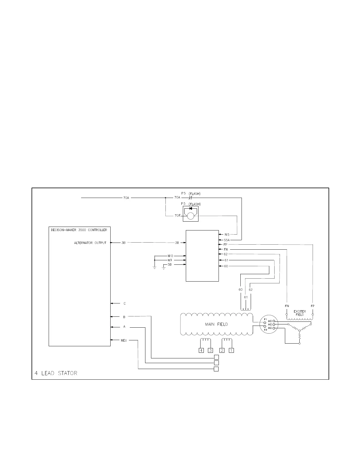
The voltage regulator (integrated in the controller)
monitors the generator output voltage through leads A
and B (for 1-phase models) and leads A, B, and C (for
3-phase models). The duty cycle of the pulse width
modulator (PWM) signal to the activator board adjusts
the exciter field current changing the main field current
to meet load requirements. See Figure 1-4 and
Figure 1-5.
ACTIVATOR
BOARD GM88453
AC VOLTAGE SENSING
AC VOLTAGE SENSING
AC VOLTAGE SENSING
AC VOLTAGE SENSING
TP-6953-1
AUXILIARY
POWER
WINDINGS
STATOR
WINDINGS
RECTIFIER
MODULE
EXCITER
ARMATURE
L2
L1
L0
NOTE: Refer to wiring diagram
ADV-5875 in the Section 17 for
voltage configurations.
See the full wiring diagram in Section 17.
Figure 1 -4 4-Lead Brushed Alternator Schematic (13- 32EKOZD and 11- 28EFKOZD Models)
 Loading...