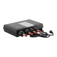
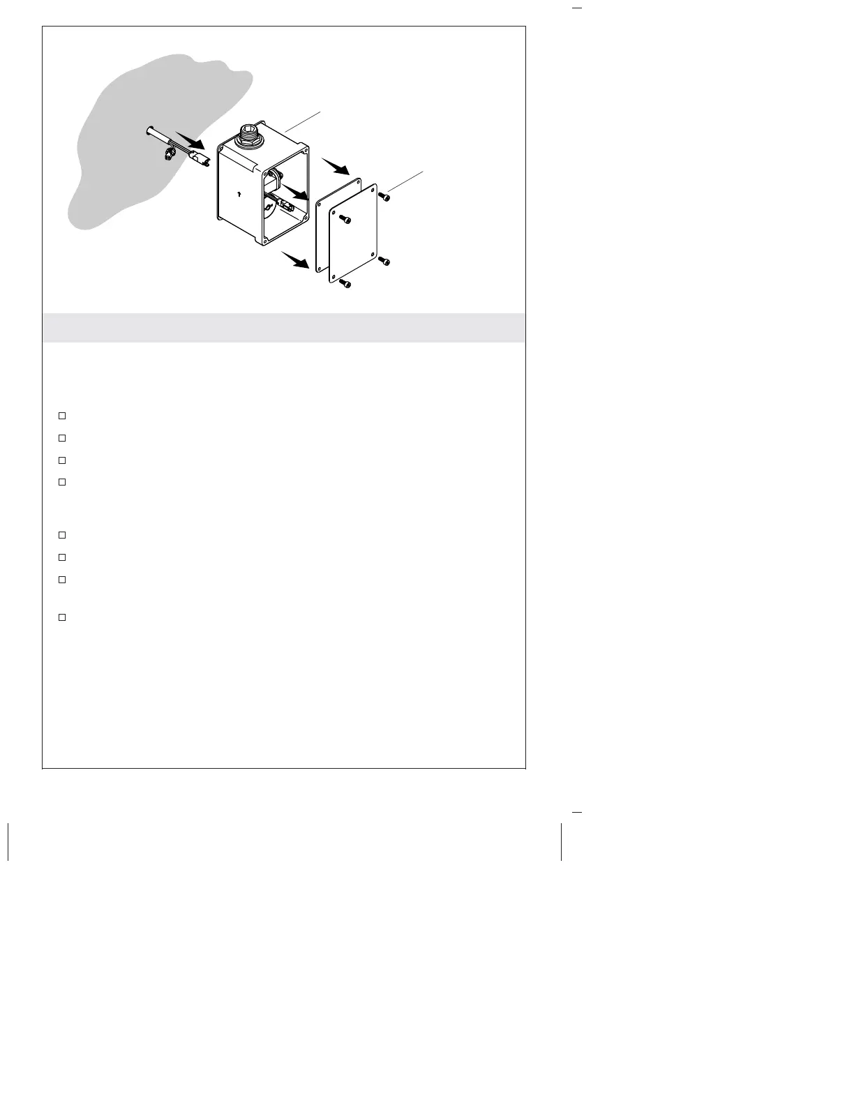
6. Install the Control Box
NOTE: Locate the sensor box underneath the countertop, between
the ell and the water supply stop.
NOTE: Do not connect the control box wiring in this step.
Drill a 1/2″ (13 mm) hole at the control box location.
Route the sensor wire through the hole.
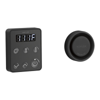
Remove the control box cover. Keep the screws and cover.
Mark the screw hole locations using the control box as a template.
Make sure the wire harness hole in the wall is covered by the
box.
Install appropriate wall anchors (not provided) at the marks.
Feed the wires through the back of the valve and control box.
Attach the control box to the wall with two screws (not
provided).
Connect the solenoid wires (red and green).
Control Box
Screws
Kohler Co. 11 1207552-2-B
 Loading...