100
Fig. 8.23
M
L
A
A
B
B
N
L
M
M
N
M
N
N
Fig. 8.24
Fig. 8.26
Fig. 8.25
W1
W2
Tab. 8.12
Tab. 8.13
ED0053030410
INFORMATION ABOUT OVERHAULING
8.6.5 Valve guides replacement
The intake and exhaust guides are both made out of grey
iron with pearlitic phosphoric matrix and they have the same
dimensions:
The guides are press-t assembled; assembly is possible by
cooling the guides with the aid of liquid nitrogen.
Before assembling a new guide, measure value L and M,
calculate the press-t value, which must observe the values
in Tab. 8.12.
Observe values G from surface F when assembling guides H
(Tab. 8.11 - Fig. 8.22).
Important
• The guides must be worked for value E (Tab. 8.11 - Fig.
8.22) after driving. Contact a rectification workshop for such
operations.
Guide valve - guide seat valves dimensions
REF. DIMENSIONS (mm)
PRESS-FIT VALUE
(mm)
L 10.000 - 10.015
0.030 - 0.054
M 10.045 - 10.054
REF. DIMENSIONS (mm)
CLEARANCE VALUE
(mm)
W1 22.005 - 22.015
0.025 - 0.056
W2 22.040 - 22.061
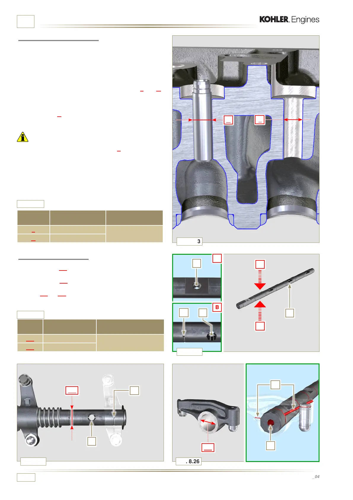
8.6.6 Rocker arm check
Measure values W1 in correspondence with holes M located
on rocker arm gudgeon L (seen from B in Fig. 8.25).
Measure values W2 (Fig. 8.26).
Based on the values measured, calculate the clearance
between W1 a n d W2, which is to observe the values in Ta b . 8 .13 .
Check that all oil pipes N and M are free from impurities or
obstructions.

 Loading...


