104
B1
S
N2
A2
Fig. 9.7
M
N1
J
B1
Q
B2
X
X
Y
P
P
B2
P
Fig. 9.5
Fig. 9.6
Fig. 9.8
T
R
LOCTITE 5660
B1
B1
LOCTITE 5660
ED0053030410
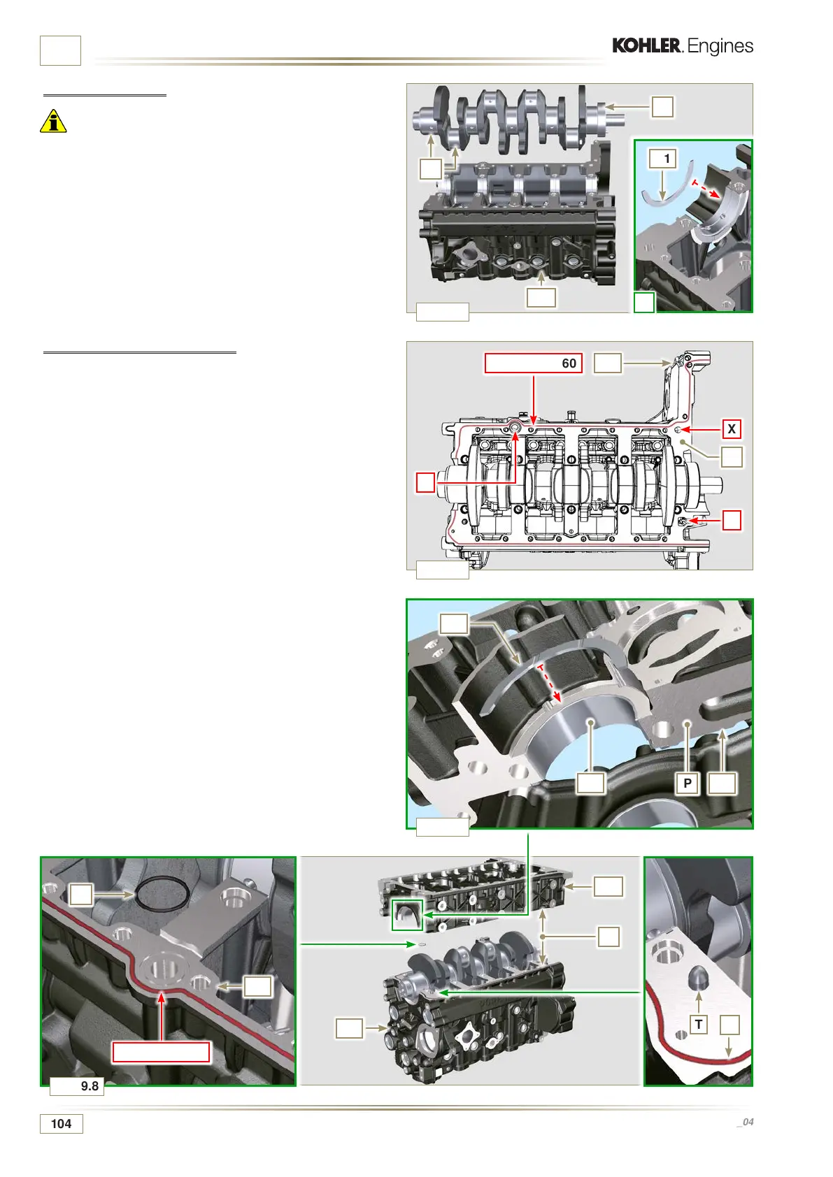
ASSEMBLY INFORMATION
9.3.4 Crankshaft
Important
• Carry out the checks described in Par. 8.4.1 and Par. 8.4.2.
1 -
Check that the crankshaft half-bearings A1 are mounted
correctly on the upper crankcase B1.
2 - Lubricate the main journal and crankpin J, with oil.
3 - Insert the crankshaft M into its seat on the upper crankcase
B1.
4 - Insert the 2 shoulder half-rings N1, between the crankshaft
M and the upper crankcase B1 (Q detail).
4 -Check that the crankshaft half-bearings A2 are mounted
correctly on the lower crankcase B2.
5 -
Assemble the 2 shoulder half-rings N2 onto the lower
crankcase B2 applying two drops of grease to keep them
in their seat.
6 - Join the two crankshaft halves B1 and B2 observing the
guide pins T.
9.3.5 Lower semi-crankcase
1 - Check that the coupling surfaces P are free from dirt and
grit.
2 - Spread a bead of Loctite 5660 of approx 1,5 mm thickness
on the surface P of the upper crankshaft half B1 being
careful not to block the oil feed grooves X and the return
oil sump Y.
3 - Insert gasket S into the seat of crankcase B1.

 Loading...


