103
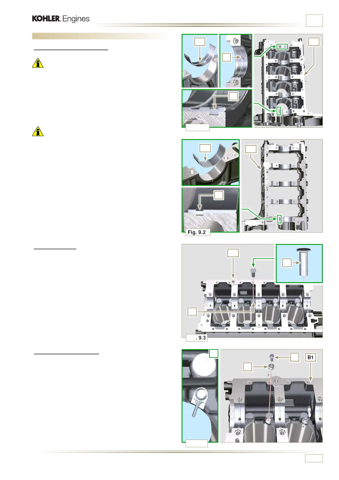
Fig. 9.2
C
B1
A2
Fig. 9.4
Fig. 9.3
Fig. 9.1
C
F
A1
D
B1
B1
E
B1
L
H
G
ED0053030410
ASSEMBLY INFORMATION
2 - Fit the new half-bearings A2 onto the lower crankcase B2
using the reference notches C.
3 - Lubricate the half-bearings A1 and A2 with oil.
9.3.2 Tappets
1 - Lubricate the tappets E with oil.
2 - Insert the tappets E into the housings F of the upper
crankcase B1.
9.3 Engine block assembly
9.3.1 Crankshaft bushings
Important
• Execute the procedure in Par. 8.2.1 and 8.2.2, before
proceeding with assembly.
• The crankshaft half-bearings are made of special material.
Therefore, they must be replaced every time they are
assembled to prevent seizures.
1 - Fit the new half-bearings A1 onto the crankcase upper half
B1 adhering to the reference notches C.
Important
• After the half-bearings are fitted, check that the lubrication
holes D correspond with the crankcase grooves B1.
• The lower and upper half bearings CANNOT be singularly
replaced, and both halves must be replaced together.
9.3.3 Oil spray nozzles
1 - Insert the sprayers G onto the upper crankcase B1
manually screwing the screw fittings H.
2 - Ensure that the spray nozzles G are inserted correctly in
their seat, as shown in detail L and tighten the connecting
screws H (tightening torque of 10 Nm).

 Loading...


