109
T3
Z
Fig. 9.24
Fig. 9.27
F1
F2
E1
E1
Fig. 9.26
M
F2
J1
J1
U1
F2
Fig. 9.25
Tab. 9.17
ED0053030410
ASSEMBLY INFORMATION
Important
• Leave the ring compressor
assembled on the piston.
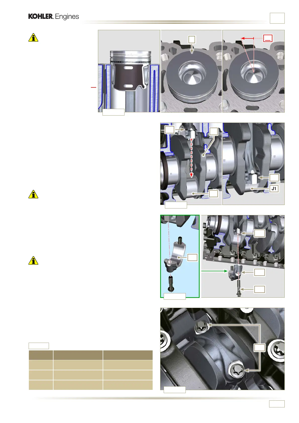
6 - Push piston Z downwards
without introducing the
segments in the cylinder,
rotate piston Z by 10° in a
clockwise direction (value T3
– correct assembly position).
7 -
Push the piston Z downwards by centering the crankpin J1
with the connecting rod F2.
8 -
Rotate the crankshaft M by moving the crankpin J1 to a
BDC position of the affected cylinder.
9 -
Push the piston Z downwards by centering the crankpin J1
with the connecting rod F2.
10 -
Turn the crankcase on support to assemble the con rod
capp F1.
11
- Check that the half-bearing U1 is mounted correctly on the
connecting rod cap F1.
Important
• Check that the break levels of connecting rod cap F1 coincide
perfectly onto connecting rod F2 before screwing on and
tightening capscrews E1.
12 -
Couple the connecting rod cap F1 to the connecting rod F2
using the marks made at disassembly Par. 7.12.1).
13 -
Apply "Molyslip AS COMPOUND 40" on the threads and
under the head of capscrew E1 and manually tighten them
until their stop.
Important
• Failure to adhere to the assembly procedures may
compromise the functionality of the engine, and also cause
damage to persons and property.
14
- Tighten the screws E1, alternately, strictly following the
tightening torques indicated (Tab. 9.3).
15 -
Repeat the operations from 1 to 14 for each cylinder.
16 -
Check that the connecting rods have axial play and the
crankshaft M rotates smoothly.
NOTE:
After the check carried out at point 16, position the
shaft M with the rst cylinder to TDC.
CYCLE SCREWS TORQUE
1 E1 28 Nm
2 E1 30°
3 E1 30°

 Loading...


