108
Fig. 9.20
F2
G
Z
F2
V1
U1
T2
Fig. 9.22 Fig. 9.23
W1
T3
Z Z
Z
Fig. 9.21
J1
M
K1
G
Fig. 9.19
ED0053030410
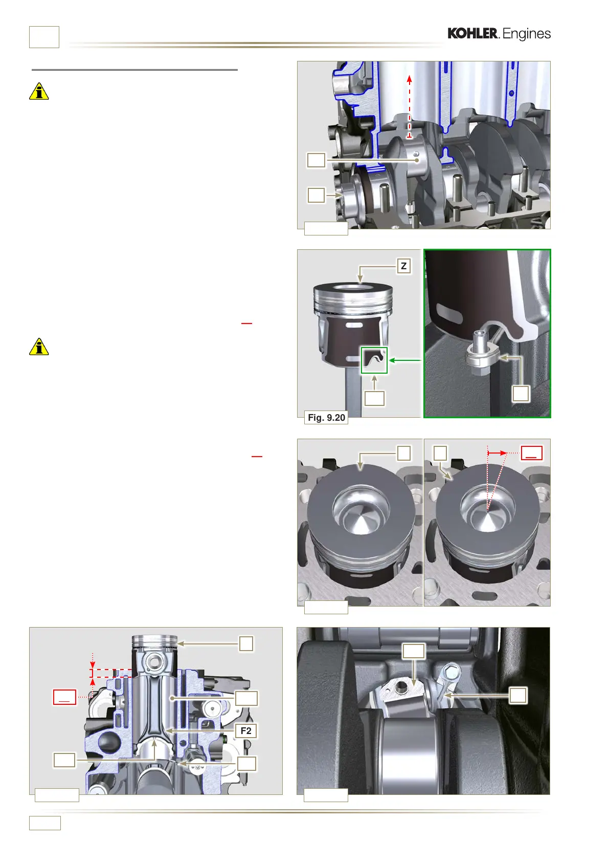
ASSEMBLY INFORMATION
2 - Lubricate the piston skirt and rings Z.
3 - Check that the half-bearing U1 is mounted correctly and
lubricate it thoroughly.
4 - Using the piston ring compression pliers, insert the piston
inside the cylinder W1 by around 10mm (height T2).
Important
• Make sure you are at the stage described in Point 1.
• Piston Z must be assembled with notch K1 on the side of the
skirt facing oil spray nozzles G.
5 -
Rotate the piston Z by 10° counter-clockwise with respect
to its correct assembly position (Fig. 9.21 - height T3).
NOTE: Doing this prevents the impact between the connecting
rod F2 and the sprayer G.
9.3.10 Piston and connecting rod assembly
Important
• Before assembling the piston and connecting rod assemblies,
execute the controls described in Par. 8.5.
1 - Rotate the crankshaft M by moving the crankpin J1 to a
TDC position of the affected cylinder.
 Loading...


