107
Fig. 9.15
Z1
Z2
Z3
Z3
Z2
Z1
Z
Fig. 9.16
Z3
Z2
C1
Z
Z1
Fig. 9.17
F2
F1E1
Fig. 9.18
L1
H1
Z
L1
G2
Z
L1
F2
G1
D1
ED0053030410
ASSEMBLY INFORMATION
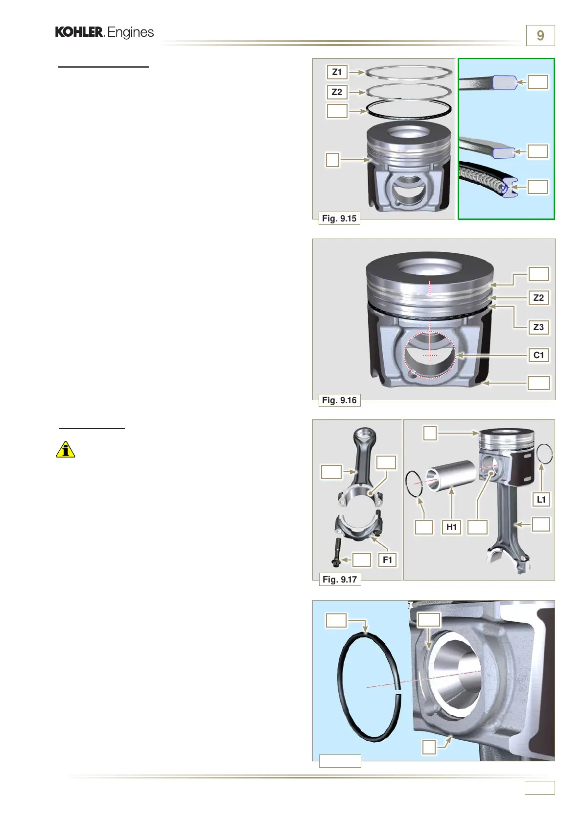
9.3.8 Piston rings
1 - Perform the operations described in Par. 8.5.3.
2 - Put the scraper ring Z3 onto the piston Z.
3 - Put the 2° seal ring Z2 on the piston Z.
4 - Put the 1° seal ring Z1 onto the piston Z.
5 - Perform the operations described in Par. 8.5.4.
6 - Align the piston rings with the opening of the centre of the
hole for the gudgeon pin C1.
7 - Lubricate the piston skirt and piston rings with oil.
9.3.9 Piston
Important
• The fastening bolts E1 must be replaced every time they are
assembled.
• Before proceeding to the assembly of the piston and
connecting rod, carry out the checks described in Par. 8.5.1,
• Always replace the bearings D1 after each assembly.
• Mate components respecting references at Par. 7.12.5.
1 - Loosen the screws E1 and remove the connecting rod cap
F1.
2 -
Insert the connecting rod F2 into the piston Z and align the
seats G1.
3 - Insert the gudgeon pin H1 into the seat G1 for the assembly
of the connecting rod and piston unit.
4 - Insert the lock rings L1 inside the seat G2 of the piston Z to
lock the gudgeon pin H1.
 Loading...


