111
A
B
CF
E
D
E
G
D
Fig. 9.32
Fig. 9.33
Fig. 9.34
2
1 11 12109
18 1734
5
6
7
8 13
14
15
16
L
ED0053030410
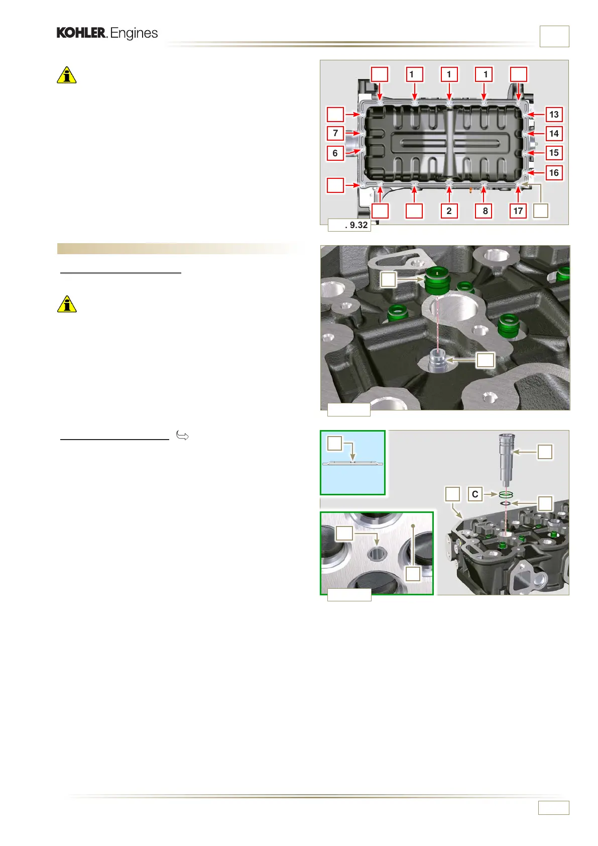
ASSEMBLY INFORMATION
Important
• Tighten the screws L, strictly following the sequence and
tightening torque indicated.
4 - Fix oil sump H by means of the screws L following the
sequence indicated (tightening torque 25 Nm).
5 - After tightening of the screw n° 10, loosen screw n°1 and
re-tighten it to the torque value specified in step 4.
9.5 Cylinder head unit assembly
9.5.1 Valve stem gasket
Important
• Carry out the checks described in Par. 8.6.4 before proceeding
with the following operations.
• Always replace gasket A with every assembly.
• Lubricate the gaskets A on the inside.
1 - Fit the gaskets A on the valve guides B using the tool
ST_08.
9.5.2 Injector sleeves ( )
1 - Insert the seals C in the seats of the sleeve D.
2 - Insert the seal E with the convex side facing upward at the
base of the sleeve D.
3 - Lubricate the gaskets C.
4 - Insert and carefully screw the sleeve D into the seat of the
head F.
NOTE: The sleeve D must not protrude above the surface of
the head G.
5 - Clamp the sleeve D (tightening torque at 30 Nm).

 Loading...


