112
FST_07
ST_03
L
Q
Fig. 9.38
Fig. 9.35
Fig. 9.36
Fig. 9.37
X
Y
F
S
F
ED0053030410
ASSEMBLY INFORMATION
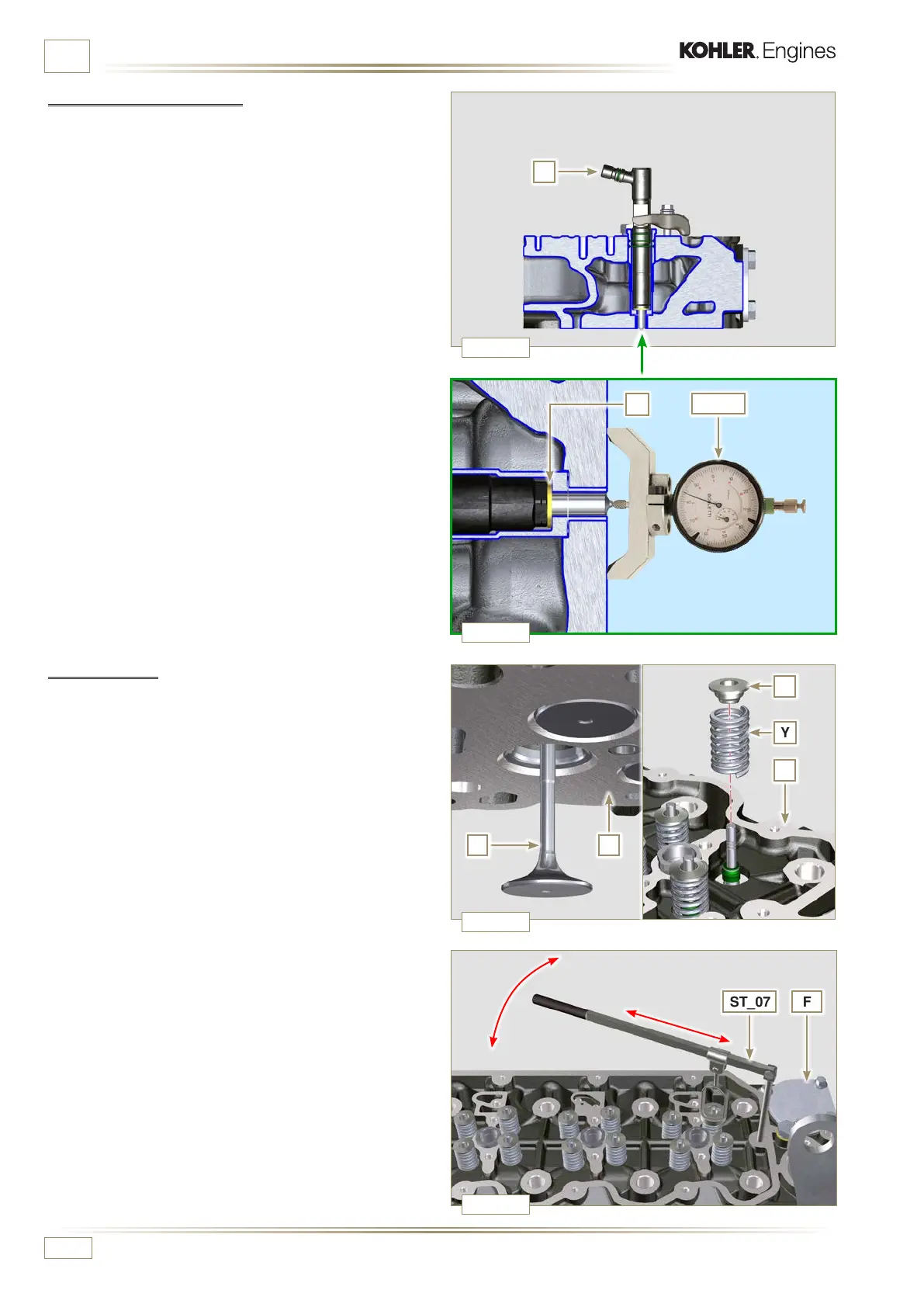
9.5.3 Injectors projection
1 - Perform the operations of Par. 6.1.7.
2 - Check, using ST_03 tool (Fig. 9.36), the projection of the
injector, which must range between 1.68 ÷ 2.42 mm.
NOTE: if the value detected does not correspond, replace
gasket Q with a different thickness
9.5.4 Valves
1 - Pre-lubricate and insert the valves X into the head F
taking care to fit them in the original positions as per the
reference marks made in Par. 7.12.4.1.
2 - Position the spring Y on the seat of the head F.
3 - Position the disk S on the spring Y centering the valve X.
4 -
Mount the tool ST_07 on the head F fixing it on one of the
holes for securing the rocker arm cover.
NOTE:
Change the xing hole according to the position of the
valves to be tted.
5 -
Position the tool ST_07 on the valve as shown in Fig. 9.38.

 Loading...


